Purpose:
This jobsheet covers how to add temperature data to vertical cross sections in the new 23.4.2 Cross Sections. It's best to test this capability with a severe weather case, or loaded in radar data.
Tasks:
- If continuing from the previous section with cross sections still loaded, skip to step 12. If starting from a blank editor, start with step 2.
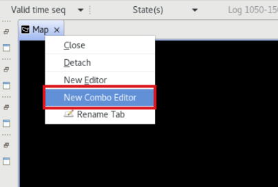
- In a single main editor, right click on the editor tab and select New Combo Editor.
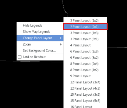
- Right click the panel->Change Panel Layout->2x1.
- Set scale to WFO or State. Right click the left panel and select Load to This Panel.
- Load Z/SRM all-tilts and Baselines on top. Change the Frames to 64.
- In the right panel select Load to This Panel. Under your desired radar menu, load Reflectivity Cross Section.
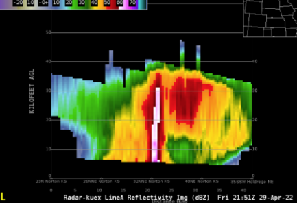
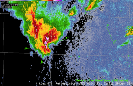
- Zoom in to a storm in the left all-tilts panel, and tilt up and down using the keyboard arrows until you find a feature you wish to generate a cross section on.
- Right click on the two points you want to use to draw a baseline from left to right (A on the left, A’ on the right. If you mix these up, the cross section will show up backwards).
***NOTE: The cross section panel will update after about 7 seconds. The CAVE status bar in the lower right will say “Awaiting further baseline changes” until it finishes updating.
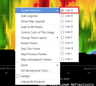
- The cross section display on the right defaults to the Line A baseline. Right click and hold in the right vertical cross section panel (not on the text legend), hover over Update Baseline, and ensure the correct baseline is being displayed (this can also be seen in the legend). If you wish to switch to another baseline, you can do that here.
- In the CAVE menu bar change your vertical scale from 0-60 kft AGL to 0-45 kft AGL.
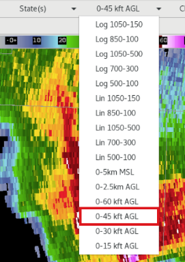
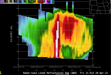
- Your cross section vertical scale should change to 0-45 kft AGL. Step through the loop and notice your cross section will update.
***NOTE: The cross section can be blank on the current volume scan if it doesn't have the 5 tilts required to generate the cross section.
- The right panel should still be set to the loading panel. If not, right click and hold on the right cross section panel and select Load to This Panel.
- Under the CAVE Volume menu select Browser. In the Volume Browser, configure the following:
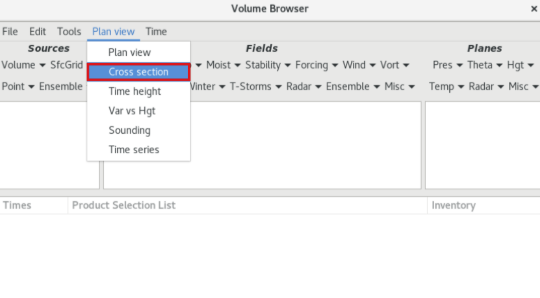
- Change the Plan view menu to Cross Section.
- Change the Log 1050-150 vertical scale menu (next to the Time menu at the top) to match the cross section scale set in the CAVE toolbar (e.g., 0-45 kft AGL) shown next to the Clear button.

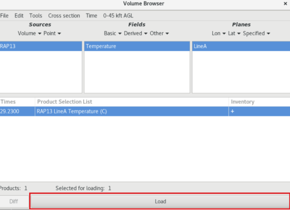
- Under Sources, select Volume ->RAP13 (or your model of choice).
- Under Fields, select Basic->Temperature.
***NOTE: If one of the fields in the Volume Browser does not allow you to select it, you can clear the Sources/Fields/Planes from the Edit menu at the top.
- Under Planes, select your cross section line (e.g., Line B) under Planes->Specified.
- Select your Product Selection and click Load.
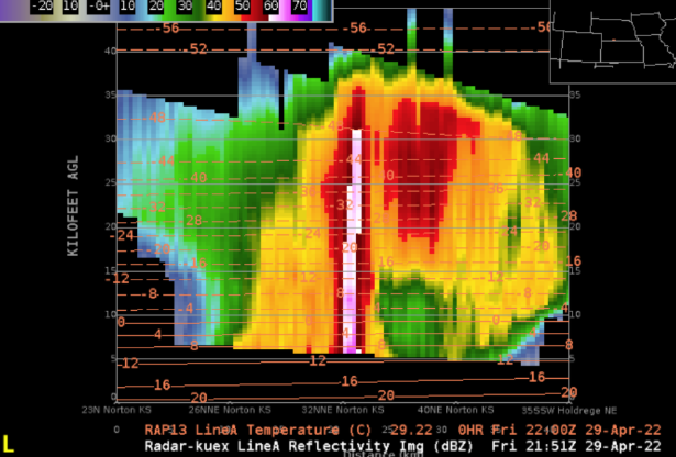
- Temperature contours should display over your vertical cross section panel. You may wish to reduce the density of the contours by right clicking on the temperature text legend and changing the Density from 1.0 to 0.5 or lower. Additionally, you can change the color to not obscure data (e.g. coral works well with Z).