


Custom Contouring - OCLO
Customized Countours
Purpose:
Tasks:
- In this jobsheet you will learn how to create multi-color contours like this:
- The approach to changing the contours in CAVE is to make simple edits to the contour style rules file. Contours are typically specified by an increment (values change as you zoom in) or by values (fixed contours). This jobsheet is intended for both forecasters and focal points, though focal points should promote any local best practices in the site override. Here is a summary of the tags that can be changed:
- color - yellow, green, red, black, etc.
- e.g. <increment color="yellow" lineStyle="LONG_DASHED" min="40" max="50">10</increment>
- linestyle:
- SOLID
- DASHED
- DASHED_LARGE DOTTED
- DASH_DOTTED
- SHORT_DASHED
- MEDIUM_DASHED
- LONG_DASH
- SHORT_DASH
- LONG_DASHED
- LONG_DASH_THREE_SHORT_DASHES
- LONG_DASH_DOT
- LONG_DASH_THREE_DOTS
- MEDIUM_DASH_DOT
- DOTS
- e.g. <increment color="red" lineStyle="LONG_DASH_THREE_SHORT_DASHES" thickness="1" min="80">10</increment>
- min and/or max typically used with the increment
- e.g. <increment color="yellow" lineStyle="LONG_DASHED" min="40" max="50">10</increment>
- values- each fixed contour to display
- e.g. <values>0 10 20 30 40 50 60 70 80 90 100</values>
- smoothing (not commonly used) - smooths the contours. Recommended values are 100-400. See image comparison for no smoothing and a value of 1000.
- e.g. <smoothingDistance>150</smoothingDistance>
- color - yellow, green, red, black, etc.
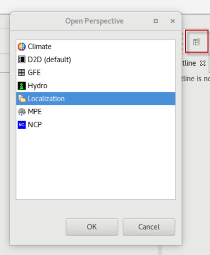
- Launch CAVE. Open the Localization Perspective.
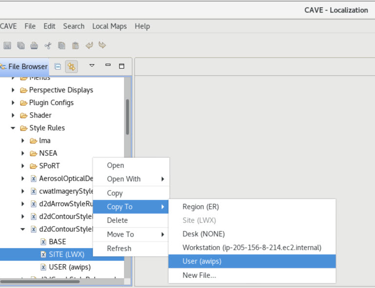
- In the Localization Perspective, go to CAVE-->Style Rules-->d2dContourStyleRules.xml and create a USER level override (if you don't have one) by selecting your SITE version followed by right clicking on the SITE version and under the "Copy To" menu, select "User".
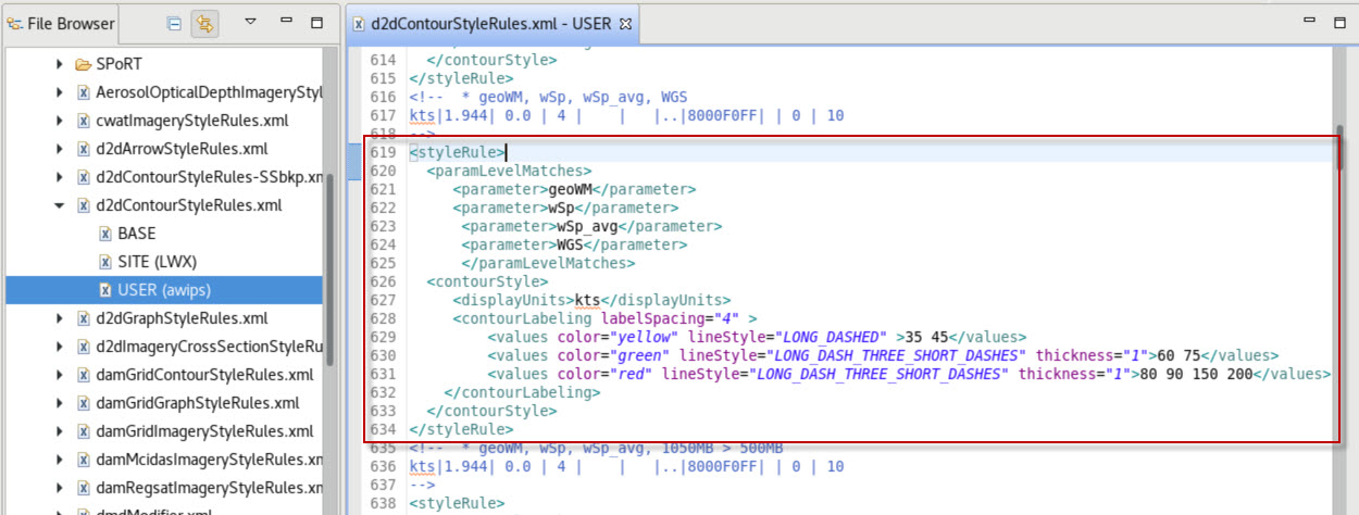
- In the USER level version, do a “Ctrl-F” and search for “geoWM.” This will locate the Wind Speed style rule.
- Below the highlighted geoWM, find the “<contourLabeling>” and "</contourLabeling> tag pair and replace the contents of this pair with the following (you can copy and paste):
<contourLabeling labelSpacing="4">
<increment color="yellow" lineStyle="LONG_DASHED" max="50">10</increment>
<increment color="green" lineStyle="LONG_DASH_THREE_SHORT_DASHES" thickness="1" min="50" max="80">10</increment>
<increment color="red" lineStyle="LONG_DASH_THREE_SHORT_DASHES" thickness="1" min="80">10</increment>
</contourLabeling>
It should look like this when you are done: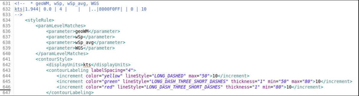
Note: If you do not have a geoWM style rule, then you can copy in the style rule from below:
<styleRule>
<paramLevelMatches>
<parameter>geoWM</parameter>
<parameter>wSp</parameter>
<parameter>wSp_avg</parameter>
<parameter>WGS</parameter>
</paramLevelMatches>
<contourStyle>
<displayUnits>kts</displayUnits>
<contourLabeling labelSpacing="4">
<increment color="yellow" lineStyle="LONG_DASHED" max="50">10</increment>
<increment color="green" lineStyle="LONG_DASH_THREE_SHORT_DASHES" thickness="1" min="50" max="80">10</increment>
<increment color="red" lineStyle="LONG_DASH_THREE_SHORT_DASHES" thickness="1" min="80">10</increment>
</contourLabeling>
</contourStyle>
</styleRule> - Save the changes and go to the D2D perspective by clicking "Ctrl s" or clicking the save icon in the localization perspective..
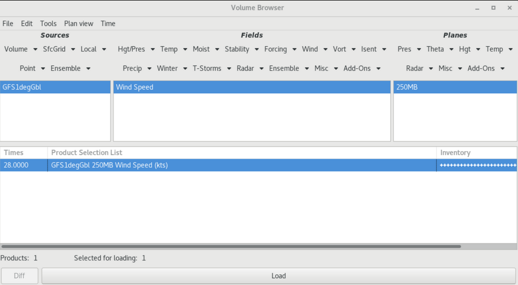
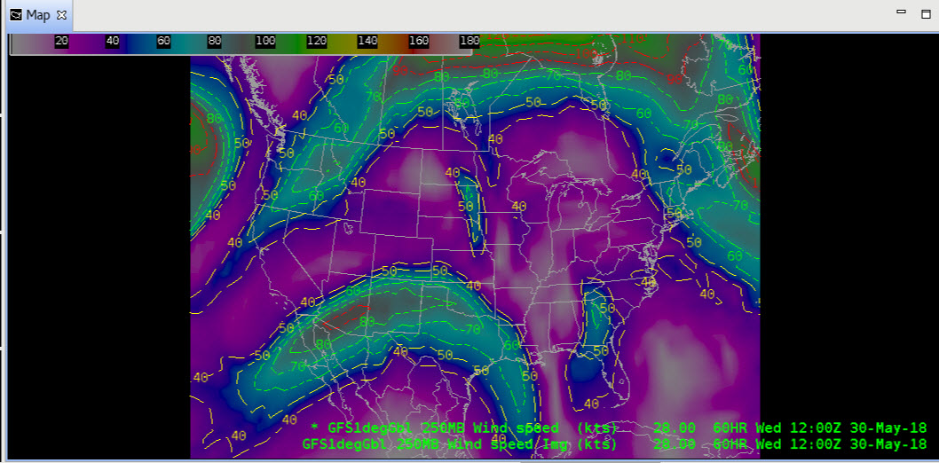
- Navigate to the Volume Brower under the Volume Menu and load GFS1degGbl 250MB Wind Speed:
Under Sources, select Volume-->GFS1degGbl
Under Fields, select Wind-->Wind Speed
Under Planes, select Pres-->250MB
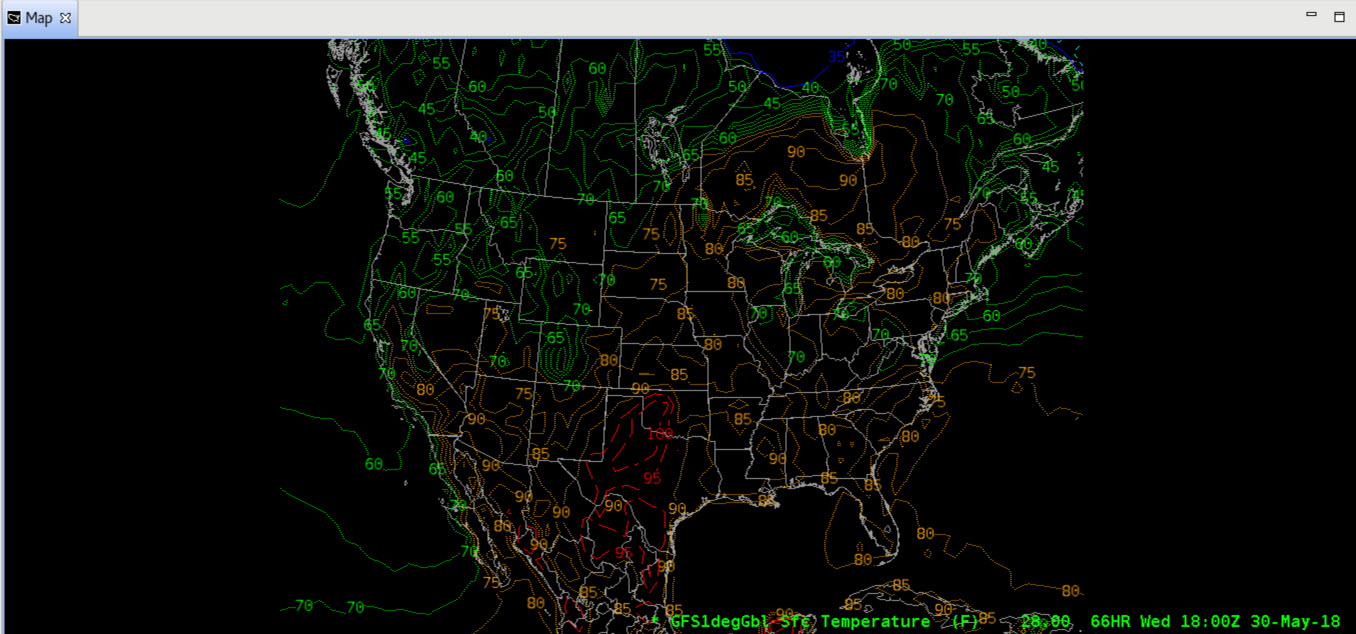
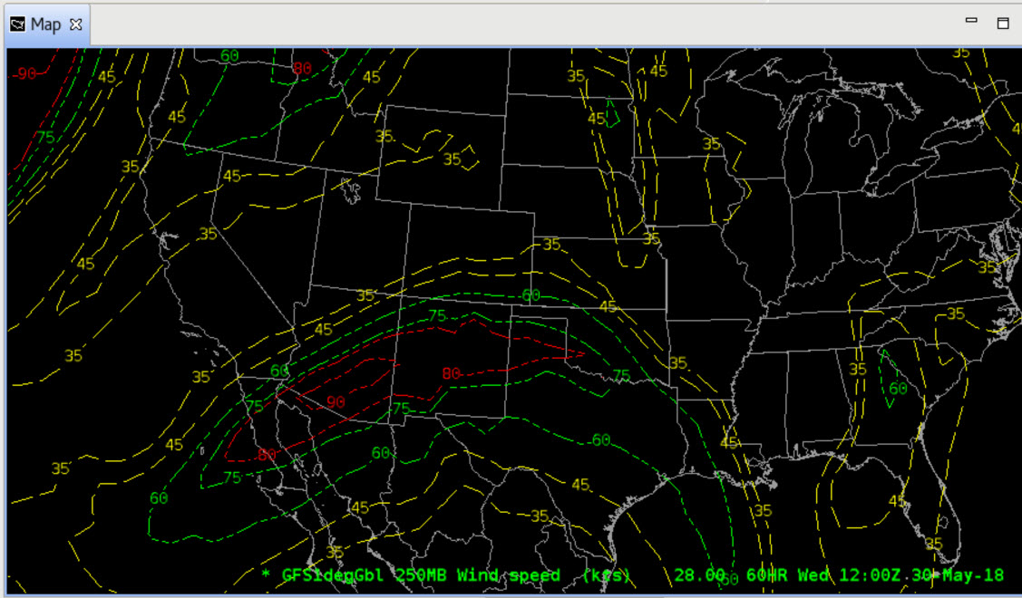
- Click Load in the Volume Browser window. The image below shows isotachs at 250mb. You can see the polar jet stream diving in from the Gulf of Alaska with an embedded jet streak highlighted in red. You can see another jet max over Hudson Bay.
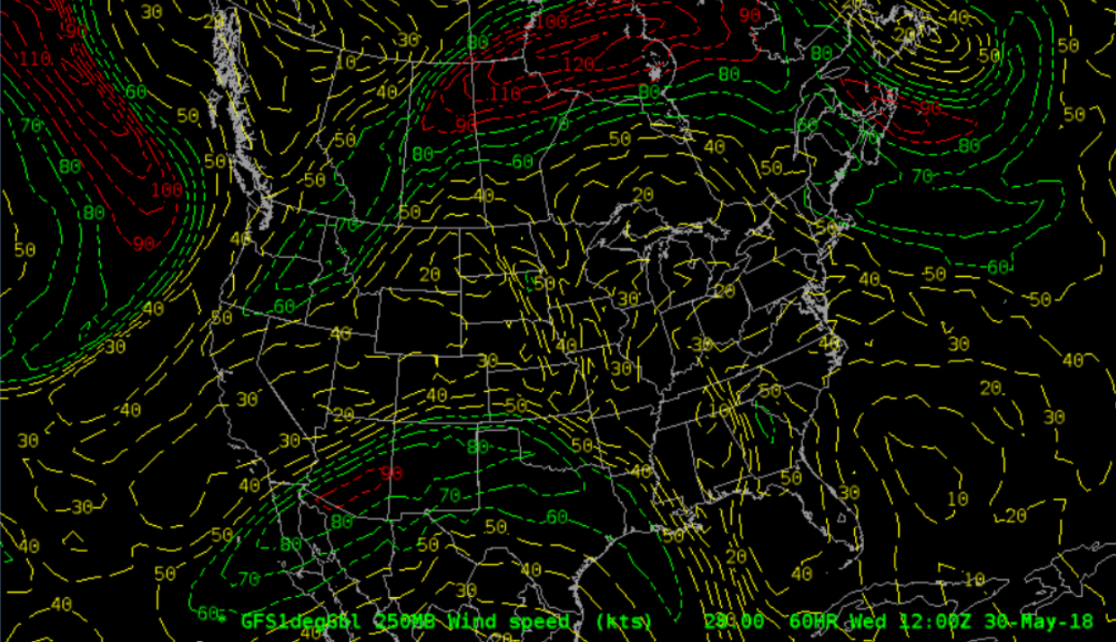
- Confirm that the contours are different colors and match the ranges form the code.
- Suppose you want to filter out weaker windspeeds < 40 kts, then you would just add min="40" to the d2dContourStyleRules.xml, save, and reload:.
- <increment color="yellow" lineStyle="LONG_DASHED" min="40" max="50">10</increment>

- <increment color="yellow" lineStyle="LONG_DASHED" min="40" max="50">10</increment>
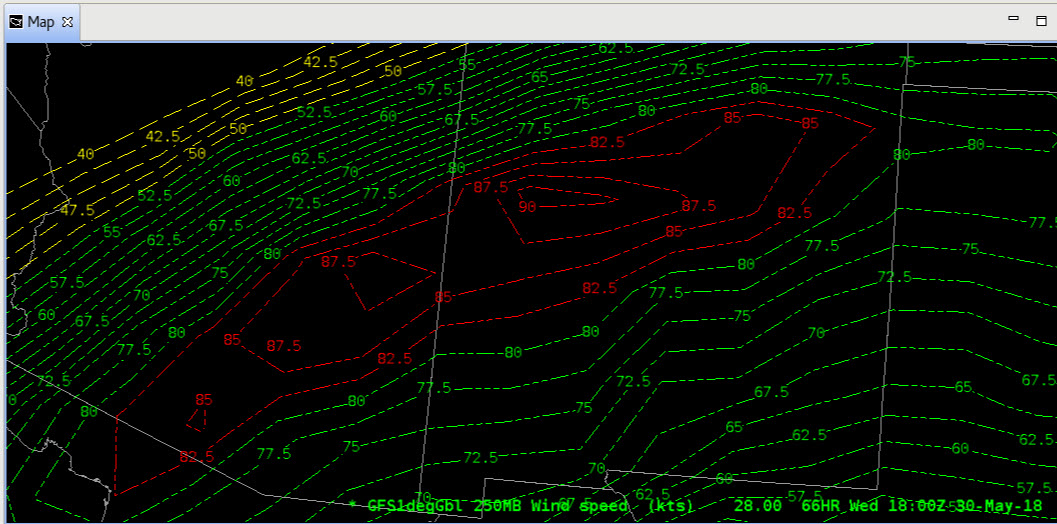
- Zoom in to the highest windspeeds and notice how with the increment tag approach, the contours can change as you zoom in.
- Note that if you combine the contours to an image, it does not implement the contouring min and max values (see image).
- Now, to implement something similar using values instead of increment, try replacing the contourLabeling tag pair contents you previously modified with:
<contourLabeling labelSpacing="4" >
<values color="yellow" lineStyle="LONG_DASHED" >35 45</values>
<values color="green" lineStyle="LONG_DASH_THREE_SHORT_DASHES" thickness="1">60 75</values>
<values color="red" lineStyle="LONG_DASH_THREE_SHORT_DASHES" thickness="1">80 90 150 200</values>
</contourLabeling>
It should look like this when you are done:
- Zoom in to your image and notice the fixed values are the only one that display:
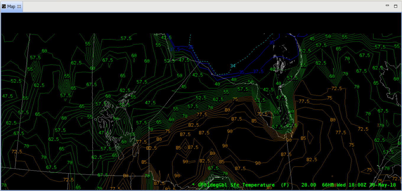
- Next let's try a temperature modification. First let's load a surface temperature plot from the Volume Browser:
Under Sources, select Volume-->GFS1degGbl
Under Fields, select Temp-->Temp
Under Planes, select Misc-->Sfc

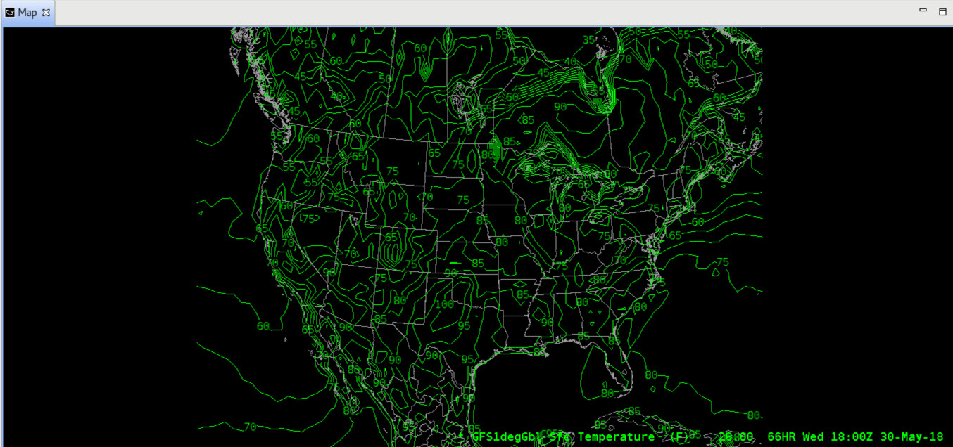
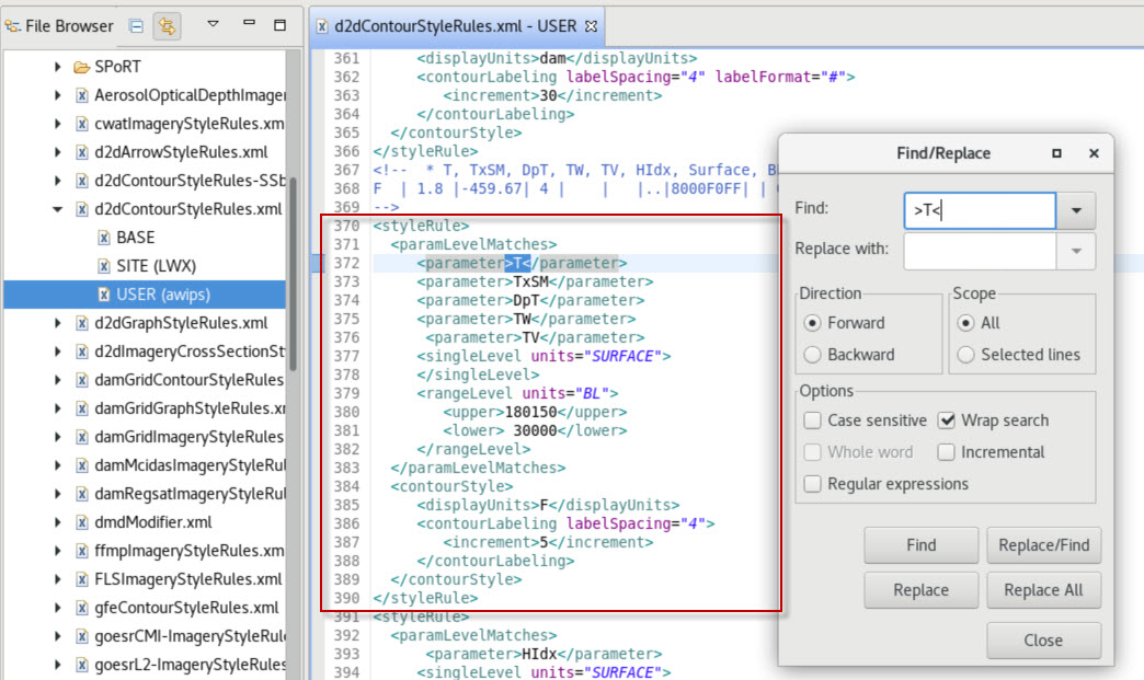
Note how the contours are all one color. - In the USER level override, do a “Ctrl-F” and search for “>T<.” This will locate the temperature style rule. You may have multiple T parameters in this file for specific models with creatingEntity tags (e.g. <creatingEntity>ECMWF-HiRes</creatingEntity), so look for one that is generic (see the style rule bracked by <styleRule> and </styleRule> tags in the image below):
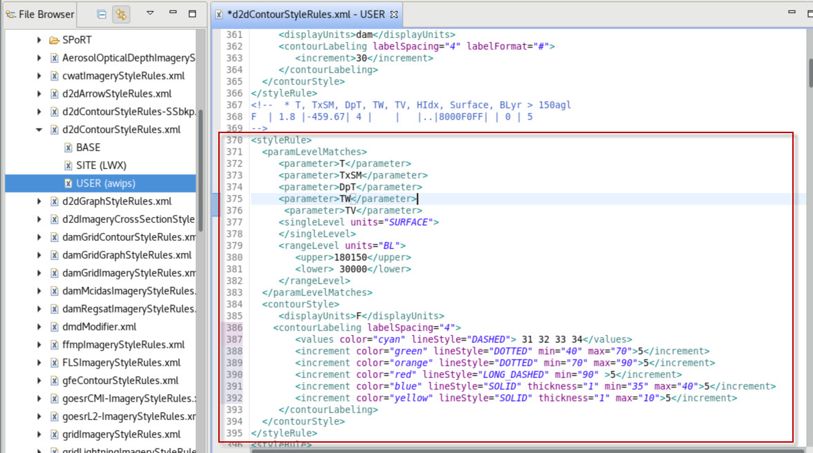
- Below the highlighted >T<, find the <contourLabeling> and </contourLabeling> tag pair. Replace the contents of this pair with the following (you can copy and paste):
<contourLabeling labelSpacing="4">
<values color="cyan" lineStyle="DASHED"> 31 32 33 34</values>
<increment color="green" lineStyle="DOTTED" min="40" max="70">5</increment>
<increment color="orange" lineStyle="DOTTED" min="70" max="90">5</increment>
<increment color="red" lineStyle="LONG_DASHED" min="90" >5</increment>
<increment color="blue" lineStyle="SOLID" thickness="1" min="35" max="40">5</increment>
<increment color="yellow" lineStyle="SOLID" thickness="1" max="10">5</increment>
</contourLabeling>
It should look like this when you are done:
Note: If you don't have a >T< style rule in your user override, you can try copying the full one below:
<styleRule>
<paramLevelMatches>
<parameter>T</parameter>
<parameter>TxSM</parameter>
<parameter>DpT</parameter>
<parameter>TW</parameter>
<parameter>TV</parameter>
<singleLevel units="SURFACE">
</singleLevel>
<rangeLevel units="BL">
<upper>180150</upper>
<lower> 30000</lower>
</rangeLevel>
</paramLevelMatches>
<contourStyle>
<displayUnits>F</displayUnits>
<contourLabeling labelSpacing="4">
<values color="cyan" lineStyle="DASHED"> 31 32 33 34</values>
<increment color="green" lineStyle="DOTTED" min="40" max="70">5</increment>
<increment color="orange" lineStyle="DOTTED" min="70" max="90">5</increment>
<increment color="red" lineStyle="LONG_DASHED" min="90" >5</increment>
<increment color="blue" lineStyle="SOLID" thickness="1" min="35" max="40">5</increment>
<increment color="yellow" lineStyle="SOLID" thickness="1" max="10">5</increment>
</contourLabeling>
</contourStyle>
</styleRule> - Save the file using "Ctrl s". Then switch back to the D2D perspective and clear reload the temperature plot from the Volume Browser:
- If you have an area close to freezing you can zoom in to see the highlighted fixed values around freezing:
- Creating effective operational procedures requires careful consideration to visibility and what the data is loaded on (blank black background or data). For values that you always want to see (e.g. 32F), consider using value tags to specify your numbers instead of increment tags in the style rule. The parameter names in the style rules file can be a little cryptic. One way to identify the parameter name is to load your desired parameter from the Volume Browser and then save it to a procedure. Then inspect the constraintValue entries in the localization perspective D2D --> Procedures folder to identify the parameter name. You can always go to the BASE override of the d2dContourStyleRules.xml to identify more of the names and syntax.
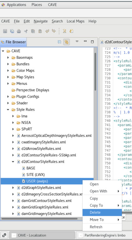
- When you are done, it would be a good idea to remove your user override. Open the localization perspective and navigate to CAVE --> Style Rules --> d2dContourStyleRules.xml --> USER file. If you have anything you would like to save, you may want to right click on your file in the localization perspective and select "Move To--> New File". Otherwise, right-click on the USER file and select Delete. Then select OK in the popup menu.