


Azimuthal Shear - Warning Decision Training Division (WDTD)
Navigation Links
Products Guide
Azimuthal Shear
Short Description
Maximum azimuthal shear (rotation divided by diameter; s-1) in the low-level (0–2 km) or mid-level (3–6 km) AGL layer. It is only available via the NWS LDM or on the MRMS Operational Product Viewer.
Subproducts
Low-Level Azimuthal Shear (0–2 km AGL)
Mid-Level Azimuthal Shear (3–6 km AGL)
Primary Users
NWS: WFO, SPC
Input Sources
WSR-88D radar data
Terrain elevation files
Resolution
Spatial Resolution: 0.005° latitude (~555 m) x 0.005° longitude (~504 m at 25°N and 365 m at 49°N)
Temporal Resolution: 2 minutes
Product Creation
Azimuthal shear (AzShear) is calculated using a Linear Least Squares Derivative method (LLSD; Smith and Elmore 2004) on radial velocity data from individual radars and then blended into a large multi-radar mosaic for the contiguous United States (CONUS). The blending process results in a field of maximum shear.
To create the products, raw velocity data from a single radar (Fig. 1) are first passed through a 3x3 median filter to reduce spurious noise in the raw velocity data.
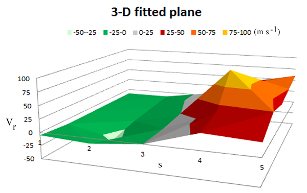
Fig. 1: Schematic example of raw radial velocity data from a single radar plotted against azimuth angle.
This example shows a velocity couplet with a centroid located between the 3rd and 4th azimuth.
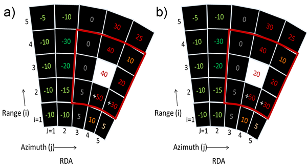
Fig. 2: Schematic illustrating (a) the raw velocity data and (b) the velocity data after applying the
median filter in the LLSD algorithm to the for i,j = 3, 4. The red highlighted region shows the range
gates that are used in the 3x3 filter for i, j = 3, 4.
Once the velocity data has been filtered, a 2-D plane is fit to the velocity data to calculate resolvable velocities. The slope of this plane is the Azimuthal Shear (Fig. 3).
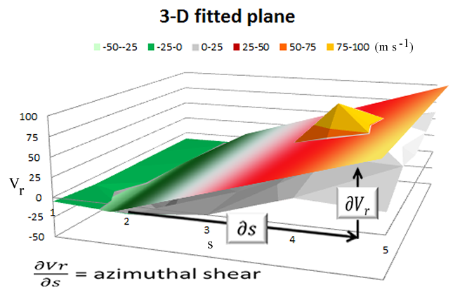
Fig. 3: 2-D Plane fitted to the raw velocity data (Fig. 1) after applying the filter (Fig. 2). The slope of the
plane is equal to the Azimuthal Shear.
A reflectivity mask is then applied to account for the unreliability of radial velocities with poor signal. Earlier versions of the LLSD algorithm would remove azimuthal shear values that were co-located with reflectivity less than 20 dBZ. However, such logic proved too draconian, especially for mesocyclones embedded in weak echo regions. Therefore, the process was modified to dilate (i.e., exaggerating their values) the quality controlled polar reflectivities so reflectivities in weak echo regions adjacent to storm cores would still be retained. Once dilation is complete, azimuthal shear values still co-located with reflectivity less than 20 dBZ are removed. (Fig. 4).
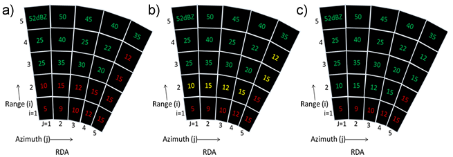
Fig. 4: Schematic illustrating the reflectivity masking process. (a) Range gates with green values are
automatically retained because reflectivity is greater than 20 dBZ, while range gates with red values
are less than 20 dBZ pre-dilation. (b) Same as (a), except range gates with yellow values are greater
than 20 dBZ after dilation. (c) After dilation green range gates retained and red gates not retained.
Layer maxima are then calculated for the 0–2 km and 3–6 km AGL layers, producing a 2D polar field of data for each layer (Fig. 5).
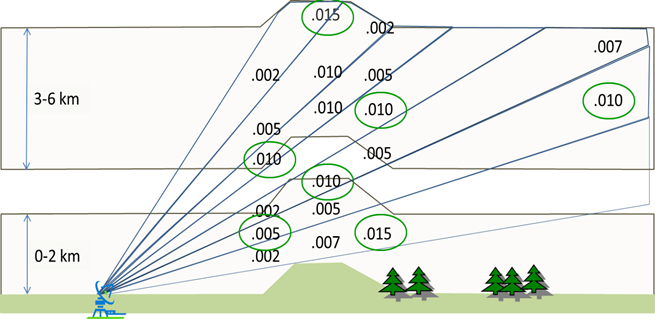
Fig. 5: Schematic illustrating how the layer maximum is determined. Values within green ovals are the
final Azimuthal Shear values for the particular layer and range.
Lastly, the data from the single-radar layer products are blended for all radars in the CONUS to produce the final 2D products.
Note: Using multiple radar viewpoints and data from slightly different times can cause Azimuthal Shear to have more than one peak for a mesocyclone (Fig. 6).
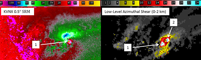
Fig. 6: 0.5° SRM and Low-Level Azimuthal Shear (0-2 km) for a supercell thunderstorm on 14 April 2012.
There is only one circulation in the SRM product, while the Low-Level Azimuthal Shear product shows
two separate circulations.
Technical Details
Latest Update: MRMS Version 12.2
In 2022, Velocity dealiasing was upgraded to the current Open Radar Products Generator (ORPG) Build 19. The previous code performing the layering of AzShear had the potential to artificially limit the data range and degrade the angular resolution if w2circ was started in the middle of a tilt with lower resolution than the volume maximum. This issue has been resolved in the current version by requiring an input resolution to match the maximum of a specific radar.
References
Lakshmanan, V., T. Smith, K. Hondl, G. Stumpf, A. Witt, 2006: A Real-time, three dimensional, rapidly updating, heterogeneous radar merger technique for reflectivity, velocity and derived products. Wea. Forecasting, 21, 802-823.
Newman, J., V Lakshmanan, P. Heinselman, M. Richman, T. Smith, 2013: Range-correcting azimuthal shear in Doppler radar data. Wea. Forecasting, 28, 194-211.
Smith, T., and K.L. Elmore, 2004: The use of radial velocity derivatives to diagnose rotation and divergence. Preprints, 11th Conf. on Aviation, Range, and Aerospace, Hyannis, MA, Amer. Meteor. Soc., CD-ROM, P5.6.
Applications
The 0–2 km AGL azimuthal shear product highlights circulations and horizontal shear zones in the low altitudes of storms that may be associated with mesocyclones and/or tornadoes.
Higher values (e.g., greater than 0.01 s-1) in the 3-6 km AGL product may indicate the presence of a deep mesocyclone, indicative of a supercell thunderstorm.
Azimuthal shear could also be associated with a gust front or another feature, depending on the viewing angle of the nearest radar. Well-sampled circulations generally appear circular, while gust fronts and shear zones are linear.
Example Images
From a Supercell Thunderstorm
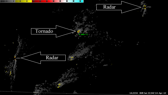
Fig. 7: Low-Level (0-2 km) Azimuthal Shear for a tornadic supercell over Kansas at 2234 UTC on 14 April
2012. The approximate location of the tornado is indicated by the arrow. Near the radars there are
artificially large values of Azimuthal Shear that are not associated with convection (see limitations).

Fig. 8: Mid-Level (3-6 km) Azimuthal Shear for a tornadic supercell over Kansas at 2234 UTC on 14 April
2012. The approximate location of the mesocyclone is indicated by the arrow.
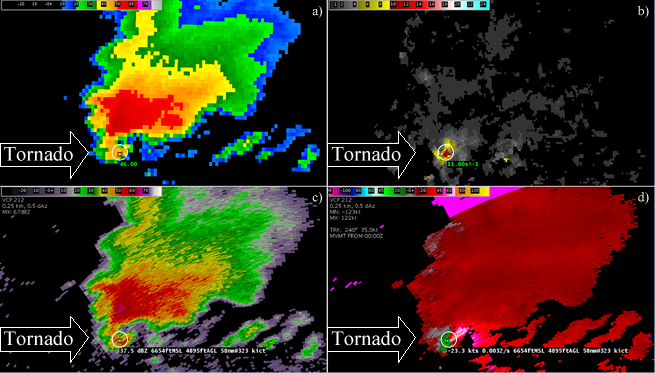
Fig. 9: Zoomed in image of Figures 7 and 8 for (a) Reflectivity At Lowest Altitude (RALA), (b) Low-Level
(0-2 km) Azimuthal Shear, (c) 0.5° Base Reflectivity, and (c) 0.5° SRM. The approximate location of the
tornado is indicated by the white circle.
For a Mesoscale Convective System
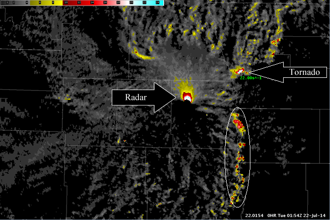
Fig. 10: Low-Level Azimuthal Shear for a MCS over North Dakota and Minnesota at 0154Z on 22 July
2014. At this time, a rain-wrapped tornado was reported from a quasi-supercell embedded within the
bowing segment. Other smaller circulations along the leading edge of the bowing segment are also
evident (highlighted by the oval). The artificially large values of Azimuthal Shear surrounding the radar
site are a result of the radar sampling vertical shear and are not associated with the storm system.
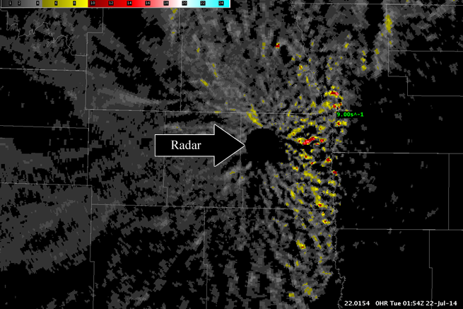
Fig. 11: Same as Fig. 10, except Mid-Level (3-6 km) Azimuthal Shear is shown. The Mid-Level Azimuthal
Shear is weaker than the Low-Level Azimuthal Shear near the location of the tornado, suggesting
shallow rotation mainly confined in the lowest layers.
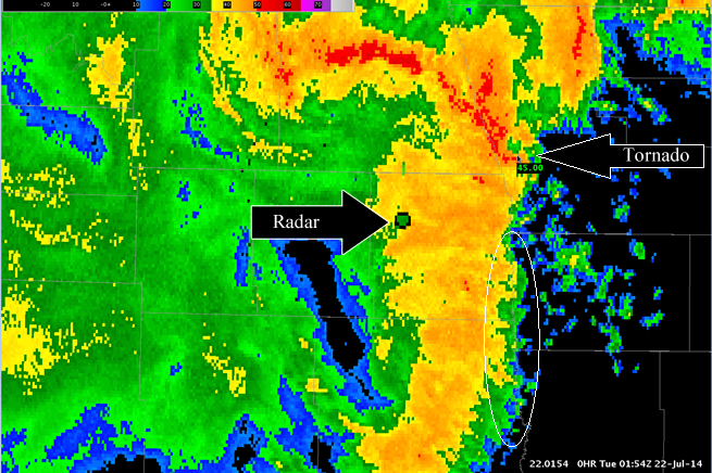
Fig. 12: Same as Fig. 10, except RALA is shown to provide context for the Azimuthal Shear signatures
shown in Figs. 10 and 11.