


Dual-Pol Quality Control - Warning Decision Training Division (WDTD)
Navigation Links
Products Guide
Dual-Pol Quality Control
Short Description
An algorithm which removes non-hydrometeorological data from single site base reflectivity radar data.
Subproducts
None.
Primary Users
This algorithm is not a MRMS product, but rather solely a quality control step.
Input Sources
Reflectivity, Correlation Coefficient, Rapid Refresh (RAP) with nested High-Resolution Rapid Refresh (HRRR) environmental data
Resolution
n/a
Product Creation
The Dual-Polarization Quality Control (dpQC) algorithm removes non-hydrometeorological data from single site base reflectivity radar data including: ground clutter, anomalous propagation (AP), wind farms, chaff, interference spikes, and bioscatterers (e.g., bugs, bats, angels and ghosts). The main filter in this algorithm is the correlation coefficient filter that removes all echoes below 0.95. While this is a very aggressive initial reflectivity-removal threshold, the algorithm has a number of subsequent steps to reintroduce or further remove reflectivity.
Technical Details
NOTE: For the latest updates to the Dual-Pol QC algorithm as of Version 12.2, see this document.
The dpQC algorithm uses 3D reflectivity structure, atmospheric environmental temperature data, and correlation coefficient (CC) to conduct the quality control (QC). CC is the correlation between the horizontal and vertical power returns for a given sample space; it is a measure of how homogenous or non-homogenous the scatterers are in radar sample space with values varying between ‘0’ and ‘1.’ Values closer to one indicate the scatterers are very similar in their size, shape and orientation, such as found with pure rain or snow. Lower CC values indicate significant differences among the scatterers within the sample space, such as found in the typical biological blooms seen in reflectivity data during the warm season. Those scatterers include birds, bats and insects.
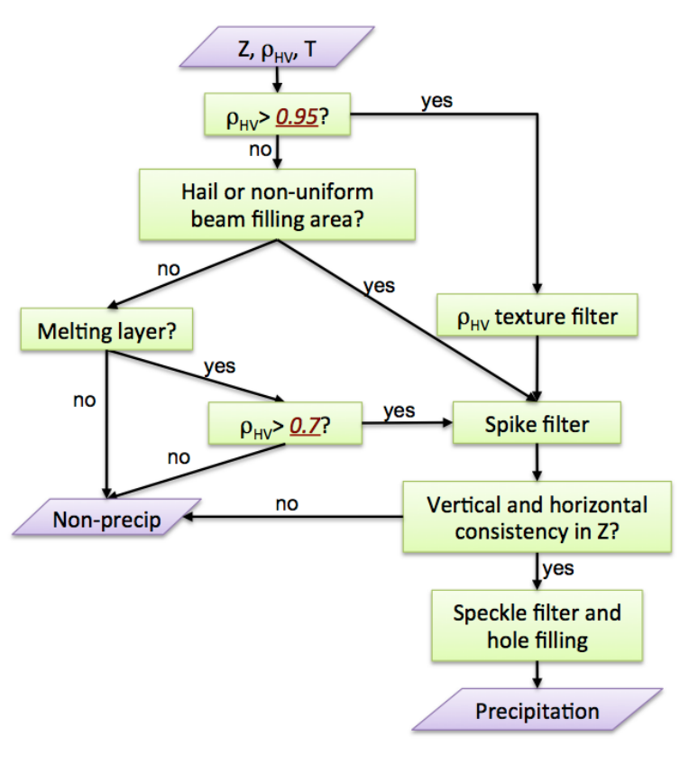
The dpQC uses a simple CC filter (> 0.95) to separate precipitation (high CC) and non-precipitation (low CC) areas, and then a set of rules that applies to exceptions to the CC filter. These exceptions include areas that may have precipitation in low CC areas (e.g. hail, non-uniform beam filling, and melting layer), or non-precipitation echoes in high CC areas (e.g. random clutter, biological). The algorithm use the 3-D structure of reflectivity and environmental temperature data to maintain these exception areas, as well as horizontal and vertical consistency checks to rid of random non-precipitation echoes. The steps below describe the dpQC process, as well as the flow chart in Figure 1:
- Significant blockage. Remove all data bins that have significant blockage (> 50%), or the bottom of the beam does not clear the ground by at least 50 m.
- Low CC. Apply the CC filter to remove all pixels below 0.95.
- This step removes a majority of residual ground clutter, blooms, wind farms, and chaff echoes left from Step 1, especially when they are not embedded within precipitation.
- Hail and non-uniform beam filling. Want to preserve reflectivity data in precipitation areas with low CC, such as those associated with hail and non-uniform beam filling.
- In areas with CC < 0.95, dpQC uses echo top heights and reflectivity to determine if the pixel is precipitation.
- The melting layer. This region is defined by low CC values, due to melting snow aggregates, melting graupel, or hail.
- dpQC uses a melting layer delineation algorithm based on the CC and temperature profile at the radar site. Once the melting layer is determined, echoes within that area with CC < 0.7 are removed.
- CC texture filter. To further remove non-precipitation echoes associated with noisy local CC texture, not removed in the previous step.
- An echo is removed if the CC texture is greater than 0.10.
- Data bins associated with hail, non-uniform beam filling, and the melting layer are exempt from this filter.
- At this point, most non-precipitation echoes associated with low CC values (< 0.95) and noisy texture are removed.
- Spike filter. Apply a spike filter to remove sun spikes and electromagnetic interference echoes not captured in the CC filter.
- Sun spikes and electromagnetic interference tend to be continuous along the radial direction, but discontinuous in the azimuthal. Additionally, they occur in the lowest two tilts and are not vertically consistent.
- Using these factors, the spike filter looks for reflectivity consistency in multiple directions to determine echo removal.
- Vertical and horizontal consistency checks. Conduct vertical continuity tests for echoes close to the radar to check for possible Anomalous Propagation (AP), ground clutter (e.g. buildings), and clear-air echoes. These echoes typically have little vertical continuity except in the most severe cases.
- A vertical gradient of reflectivity is checked in the lowest tilts to see if echo intensity decreases significantly with height (> 50 dBZ/km). If so, it is identified as AP, ground clutter, or clear-air.
- A horizontal check of neighboring pixels is also used to further identify these types.
- Speckle filter and hole filling. Remove small clear-air echoes, and fill in small gaps in precipitation areas.
- After the original CC filter, if the remaining echoes of 10 dBZ or greater in the volume scan add to less than 10 km2, the whole volume scan is removed. This removes clear-air, high-biased CC values present in upper tilts.
- Horizontal interpolation and/or upper tilts are used to fill in gaps within precipitation areas where random precipitation pixels may have received low CC values that caused them to be originally removed.
- Distant reflectivity bins. Classify distant reflectivity bins, with correspondingly low Signal-to-Noise Ratio and/or high CC values, as either weather or clutter based on proximity to nearest storm or clutter centers.
References
Tang, L.,, J. Zhang, M. Simpson, A. Arthur, H. Grams, Y. Wang, and C. Langston, 2020: Updates on the radar data quality control in the MRMS quantitative precipitation estimation system. J. Atmos. Oceanic Technol., 37, 1521-1537.
Zhang, J., K. Howard, S. Vasiloff, C. Langston, B. Kaney, Y. Qi, L. Tang, H. Grams, D. Kitzmiller, J. Levit, 2014: Initial Operating Capabilities of Quantitative Precipitation Estimation in the Multi-Radar Multi-Sensor System. 28th Conf. on Hydrology, Amer. Meteor. Soc.
Tang, L., J. Zhang, C. Langston, J. Krause, K. Howard and V. Lakshmanan, (2014): A multi-sensor physically based weather/non-weather radar echo classifier using polarimetric and environmental data in a real-time national system. In revision for Weather and Forecasting.
Applications
Doing a base reflectivity QC (using the dpQC algorithm) is a critical part in developing the Surface Precipitation Rates. Reflectivity QC is the first step to minimizing Quantitative Precipitation Estimation (QPE) errors caused by non-precipitation echoes, and is quite successful removing the non-precipitation data (Heideke Skill Score = 0.80 for an independent data set).
Example Images
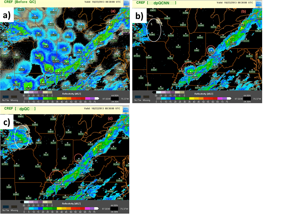
Figure 2. MRMS composite reflectivity images illustrating the results of base reflectivity QC: a) un-corrected reflectivity data has numerous biological blooms; b) data QC’d using an older algorithm… with the exception of the red circles, most blooms were removed but valid echo (white oval) was also removed; c) data QC’d with the upgraded dpQC algorithm removed all of the blooms and did not remove valid data.
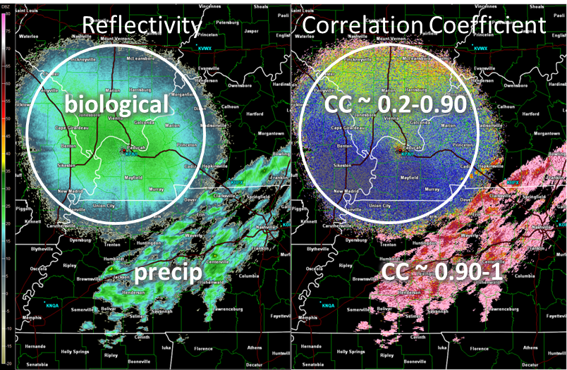
Figure 3. A closer look at the KPAH radar from Figure 2. This displays how the basic CC filter helps to removes low values (below 0.95) associated with biological clutter. (left) Reflectivity showing areas of biological and precipitation echoes. (right) Correlation coefficient showing low CC’s in the biological area and high CC’s in the precipitation area.