Page Contents
- gfeConfig
- SITE-level GFE config file
- Common Overrides
- Map Issues
- Scripts
- Baseline scripts
- Color Maps
- Cleanup
- Smart Tools
- Structure
- Description and When to Use vs. Procedure
- Good Examples
- Procedures
- Structure
- Description and When to Use vs. Smart Tools
- Good Examples
- Text Formatters
- How the CONFIGURED-Level Files are Set Up
- Inheritance
- Configured vs. Region vs. Site
- Text Products
- Overrides
- Naming Conventions
- Troubleshooting Output and Logs
- Text Utilities
- Definitions
- What Goes Here vs. Overrides
- Naming Conventions
- Overrides
- What Goes Here vs. Definitions
- AreaDictionary
- Troubleshooting
- When a Formatter Does not Appear in the Formatter Launcher
- When a Formatter Fails
- When a Formatter Produces Unexpected Results
- Other
- Utilities
- Basics and How They Fit into the Smart Tools/Procedures/Text Infrastructure
- MakeHazardConfig
- localEffectAreas and localAreaData
- Short History with SmartScript
gfeConfig
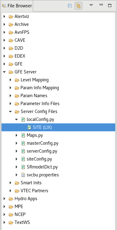
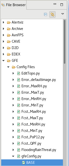
The gfeConfig.py file is located in the Localization Perspective under the GFE Folder under the Config Files folder as shown in the image below.
This file is a BASE configuration file that is not intended to be modified. It shouldn't be modified because changes will be overwritten in the next AWIPS build. The gfeConfig.py file controls all the user-side display and functions within GFE. It contains all of the BASE configuration items which can be overridden in SITE- and USER-level overrides.
SITE-level GFE config file
The SITE-level GFE config file (e.g., XXX_gfeConfig.py, XXX_gfe_config.py, gfeConfigXXX, XXXConfig, siteGFEConfig, siteConfig, and SITE_gfeConfig where XXX is your site id) is located in the Localization Perspective under the GFE Folder under the Config Files Folder. This file contains all the SITE-level overrides.
Common Overrides
- Mutable Database (mutableModel)
- The mutable database (mutableModel) variable (an example is shown below) specifies which database (only one) can be modified.
- The mutable database (mutableModel) variable should ONLY be overridden for testing purposes or for fixing errors.
- Changing this parameter will allow you to edit things you normally can’t change and is useful for fixing errors in the Obs database.
- The format for this parameter is "type_model_time".
- However, the formats with time are not normally used.
- They are useful when you want to edit a specific database that is not a singleton.
- The format for the time string is yyyymmdd_hhmm.
- If time is not important, then the format is "type_model".
- This format is used when the database to be edited has a specific type (e.g., D2D for D2D models).
- If a specific model time does not matter and there is not a type, then the format is "_model".
- It is very important when using this format to not forget the underscore.
- When not testing, the mutable database (mutableModel) variable should be commented out or deleted in your SITE-level GFE config file.
- Unless testing or fixing errors, the mutable database (mutableModel) variable is set to "_Fcst" as shown below for the forecast database in gfeConfig.py .

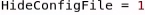
- Hide Config File (HideConfigFile)
- By default all GFE configuration files show up in the GFE Start Up Dialog shown below.
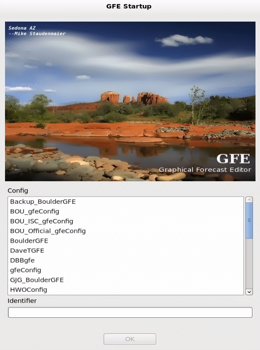
- The hide config file variable (an example is shown below) is used to hide configuration files from the GFE Start Up Dialog.
- The value assigned to the hide config file variable is not important (must be an integer), but it is usually set to one or zero.
- If the hide config file variable isn't commented out and is set equal to a value not zero, then the configuration file will be hidden.
- As an example, the ifpImage configuration files are usually hidden.
- If the hide config file variable is in a file, it needs to be added to the top of the configuration file below the import statements.
- Default Group (DefaultGroup)
- The default group variable defines the weather element and edit actions groups (an example is shown below) that will be loaded when starting GFE.
- Overriding the default group variable allows a particular weather element and edit action group to be loaded initially every time that your SITE-level or a USER-level gfeConfig file is used when starting GFE.
- A weather element group contains a listing of weather elements and their databases.
Task: Weather Element Groups under Weather Element Browser
This task demonstrates how to create Weather Element Groups using the Weather Element Browser and then promote them to SITE so other users can use them.
View Jobsheet
- The name of the group should match the name of a group in the Localization Perspective under the GFE Folder in the Weather Element Groups Folder.
- Note that BASE-level Weather Element Groups cannot be hidden from the Weather Element Groups Menu under the WeatherElement Menu in GFE.

- Default Samples (DefaultSamples)
- The default samples variable (an example is shown below) defines the initial group of sample sets that are displayed when starting GFE.
- Overriding the default samples variable allows a particular sample set(s) to be loaded initially every time that your SITE-level or a USER-level gfeConfig file is used when starting GFE.
Task: Setting Sample Points from under Maps
This task demonstrates how to create a new set of sample points and then promote them to SITE so other users can use them.
View Jobsheet
- The name of the sample set(s) should match the name of a sample set in the Localization Perspective under the GFE Folder in the Sample Points Folder.
- Each sample set name needs to be put in single quotes in the list.
- Using single quotes as an entry means that no samples will be displayed.

- Grid Manager Edit Actions (GridManagerEditActions)
- The Grid Manager edit actions variable (an example is shown below) specifies which Smart Tools will appear on the Grid Manager right-click popup menu.
- Overriding the Grid Manager edit actions variable allows a Smart Tool(s) to be available in the Grid Manager right-click popup menu.
- The name of the Smart Tool(s) should match the name of a Smart Tool in the Localization Perspective under the GFE Folder in the Smart Tools Folder.
- Each Smart Tool needs to be put in single quotes in the list.

- Keyboard Shortcuts (ShortCut#)
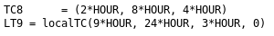
- The keyboard shortcut variable (two examples are shown below) define keyboard shortcuts for GFE.
- Keyboard shortcuts allow you to perform various GFE commands by using one or a few keyboard keys.
- Adding new keyboard shortcuts will allow your office to perform common GFE operations by using one or a few keyboard keys.
- Each shortcut is defined by a list with entries: shortcut key, state of shortcut key, action type, and name of the action.
- State of shortcut key can be None, Crtl (control key), Alt, and Shift.
- Key states can be combined (e.g., Crtl+Alt).
- Action type can be EditTool, SmartTool (execute a Smart Tool), Procedure (run a Procedure), and Toggle.
- The possible EditTool actions are Sample, Pencil, Contour, MoveCopy, and DrawEditArea.
- The possible Toggle actions are ISC and TEGM (Temporal Editor/Grid Manager).
- The maximum number of shortcuts allowed is 200.
- You should test your shortcuts on your system as many keys are already bound by the system.
- Each portion of the list should be put in double quotes.

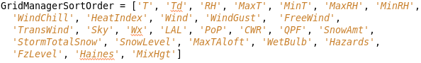
- Grid Manager Sort Order (GridManagerSortOrder)
- The Grid Manager sort order variable (an example is shown below) defines the order in which weather elements will be displayed in the Grid Manager.
- Elements in this list will appear first and all others will be ordered alphabetically by name.
- If not defined, then the weather elements will be ordered alphabetically by weather element name.
- Changing the order the weather elements appear in the Grid Manager allows you to have the same type of elements near each other (e.g., T, Td, MaxT, MinT) or elements that depend on each other near each other (e.g., T, RH, Td).
- Each weather element should be put in single quotes.
- The first section of the Grid Manager will always be the mutable database (i.e. Fcst).
- A separator line is placed at the end of the mutable database panes.
- All other databases are shown after the separator line.
- Grid Manager Sort Algorithm (GridManagerSortAlgorithm)
- The Grid Manager sort algorithm variable (an example is shown below) determines the sorting order of weather elements in the Grid Manager and Spatial Editor Legends.
- It consists of up to five characters in the order of sort importance.
- The characters are: 'm' for mutable, 'N' for parm name, 'M' for model name, 't' for model time, and 'o' for model optional type.
- All characters must be put in double quotes when declaring the Grid Manager sort algorithm variable.
- This allows all weather elements with the same name, model name, model time, or model type to be grouped together.
- For example, “mNMto” will result in the mutable weather elements first, then weather elements with the same parm name, then weather elements from the same model name, then weather elements from the same model time, then weather elements with the same optional type.
- This means that all of the weather elements with the same name from different models will be grouped together (except for the mutable weather elements).

- Auto Save Interval (AutoSaveInterval)
- The auto save interval variable (an example is shown below) defines the initial setting of the automatic weather element save interval.
- The auto save interval variable allows grids to be saved automatically every x number of minutes.
- This override allows your office's forecasters to not have to worry about forgetting to save their grids.
- The values can range from 0, to indicate off, up to a reasonable value, such as 60, to save the grids automatically every hour.

- Publish Times (PublishTimes)
- The publish times variable (an example is shown below) defines the list of entries that appear on the publish dialog.
- The entries are the names of the user-defined selection time ranges.
- The order of entries on the publish dialog will match this list.
- The entries in the list must be put in single quotes.
- The entries must be valid user-defined time ranges (i.e., times in the time scale periods list and on the time scale in the Grid Manager) or they will be ignored.
- This override allows you to choose (add or remove) the time ranges that show up in the publish dialog which can make it easier to find the time range you want to use in the publish dialog.

- Publish Dialog Initial Weather Element Group (PublishDialogInitialWEGroup)
- The publish dialog initial weather element group variable (an example is shown below) defines the weather element group which will be selected (highlighted) when first opening the publish dialog.
- The name of the weather element group should match the name of a group in the Localization Perspective under the GFE Folder in the Weather Element Groups Folder.
- This override allows you choose the weather element group that will be published if no changes are made to the publish dialog.

- Map Backgrounds (MapBackgrounds_default)
- The map backgrounds list (an example is shown below) specifies which map backgrounds are displayed when initially opening GFE.
- The map backgrounds list can contain zero or more map names.
- Overriding the map backgrounds variable allows desired map backgrounds to be displayed initially every time that your SITE-level or a USER-level gfeConfig file is used when starting GFE.
- The name of each map background should match the name of a map file in the Localization Perspective under the CAVE Folder under the Bundles Folder in the maps Folder.
- The map backgrounds must be put in the list in single quotes.

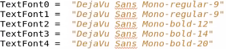
- Text Font (TextFont#)
- The text font entries (an example is shown below) are used by everything in the GFE.
- A better location to override the fonts is in the configuration items under the UI Configuration section of the gfeConfig.py file.
- The text font entries should be overridden when you want to change the size, style, or fontname for all fonts used in GFE.
- There are five sizes of text fonts used in GFE which are identified from zero to four to increase/decrease the size of the text.
- They should be ordered from the smallest font to the largest font.
- The fonts should all be from one font family.
- A valid font data representation is a string of the form fontname-style-height where fontname is the name of a font, style is a font style (one of “regular”, “bold”, “italic”, or “bold italic”), and height is an integer representing the font height (or size).
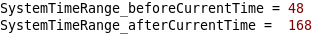
- System Time Range Variables (SystemTimeRange_before/afterCurrentTime)
- The system time range variables (an example is shown below) specify the width (scrollable limits) of the Grid Manager/Temporal Editor in relation to the current time.
- The units are in hours.
- If grids are present the scrollable time range may be expanded/modified by the software.
- Overriding these variables allows you to see more/fewer grids in the future and past.
- If no grids are present in any of the weather elements, then the Temporal Editor and Grid Manager will use the default starting and ending times based on the current system time.
- For example, if the before current time is set to 48 (2 days) and the after current time is set to 168 (7 days), then the Grid Manager scroll limits will be 2 days in the past and 7 days into the future.
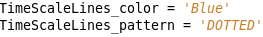
- Time Scale Lines Color and Pattern (TimeScaleLines_color/pattern)
- The time scale lines color and pattern (an example is shown below) define the color and pattern of the time scale lines in the Grid Manager/Temporal Editor.
- The time scale lines are the lines that go from the time scale through the Grid Manager and Temporal Editor every 6 hours.
- Overriding these variables can make the time scale lines easier to see depending on which Grid Manager mode you are in.
- The colors may be specified as a known color available in GFE or as a '#rrggbb' color.
- The available line patterns are SOLID, DASHED, DOTTED, and DASHED_DOTTED.
- Time Block Colors
- Time Block Active Color (TimeBlockActive_color)
- The time block active color (an example is shown below) defines the color used in the Grid Manager in Normal mode to indicate when a grid block is active.
- The time block active color is the color of the currently selected (active grid) block in Normal mode.

- Time Block Preview Color (TimeBlockPreview_color)
- The time block preview color (an example is shown below) defines the color used to indicate which grids may be modified during an edit action in Normal mode.

- The colors may be specified as a known color available in GFE or as a '#rrggbb' color.
- These variables can be overridden so that when in Normal mode you know which grid is active and which may be modified by an edit action (Smart Tool).
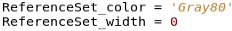
- Edit Area Color and Border Width (ReferenceSet_color/width)
- The edit area (ReferenceSet) color and border width (an example is shown below) define the color and border width used to indicate the edit area on the Spatial Editor.
- The color may be specified as a known color available in GFE or as a '#rrggbb' color.
- These variables can be overridden to make it easier to see the edit area in the Spatial Editor.
- Time Scale Horizontal Size (TimeScale_horizSize)
- The time scale horizontal size variable (an example is shown below) defines the initial width of the Grid Manager, in pixels.
- This variable can be overridden to set a preferred initial width of the Grid Manager for your site based on your CWA's shape and size.

- Legend Mode (LegendMode)
- The legend mode variable (an example is shown below) specifies what is shown in the Spatial Editor legend when starting GFE.
- The legend mode variable may be specified as 'GRIDS', 'MUTABLE', 'ACTIVE', 'MAPS', or 'SETIME'.
- GRIDS' shows all grids in the legend, 'MUTABLE' shows mutable weather elements, 'ACTIVE', shows actively displayed weather elements, 'MAPS' shows the displayed maps, and 'SETIME' shows the Spatial Editor time.
- The mode must be specified in single quotes and all caps.
- This variable can be overridden to set a preferred Spatial Editor legend upon GFE startup.

- Initial Grid Manager Display Mode (InitialGMDisplayMode)
- The initial Grid Manager display mode variable (an example is shown below) specifies which mode should be used to color the grid blocks in the Grid Manager when starting GFE.
- The initial Grid Manager mode variable may be specified as 'Normal', 'History', 'Saved', Modified', 'Published', or 'Sent'.
- In 'Normal' mode, the Grid Manager shows all grid blocks as gray except for those which are displayed or active in the spatial editor.
- In 'History' mode, the Grid Manager color-codes each grid block to indicate its data source and whether it has been modified.
- In 'Saved' mode, the Grid Manager color-codes the grid blocks based on the last time the grid was saved.
- In 'Modified' mode, the Grid Manager color-codes the grid blocks based on the last time the grid was modified.
- In 'Published' mode, the Grid Manager color-codes the grid blocks based on the last published time.
- In 'Sent' mode, the Grid Manager color-codes the grid blocks based on the last time the grid was sent via Intersite Coordination.
- The mode must be specified in single quotes.
- This variable can be overridden to set a preferred Grid Manager display mode upon GFE startup.

- Quick Set Buttons (QuickSetButtons)
- The quick set buttons variable (an example is shown below) defines the number of edit area quick set buttons.
- Quick set buttons are a way to save edit areas and make them be easily accessible without saving them as an edit area.
Task: Edit Areas and Edit Area Groups
This task demonstrates how to create Edit Areas and Edit Area Groups and then promote them to SITE so other users can use them.
View Jobsheet
- There is a limit of seven.
- This variable can be overridden to specify more/fewer quick set buttons than the default (i.e., 4).
- Entering a number greater than 7 will result in only 7 quick set buttons being displayed.

- Max Menu Items Before Cascade (MaxMenuItemsBeforeCascade)
- The max menu items before cascade variable (an example is shown below) sets the maximum number of menu items before any menu will cascade with 'More>'.
- Do not place a decimal point after the number.
- This variable can be overridden to specify more/fewer menu items before cascading occurs.

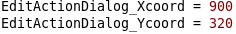
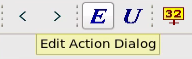
- Edit Action Dialog Xcoord and Ycoord (EditActionDialog_Xcoord/Ycoord)
- The edit action dialog Xcoord and Ycoord variables (an example is shown below) define the initial location of the edit action dialog.
- The location is in absolute screen coordinates with (0, 0) in the upper left of the display (not relative to the GFE window).
- This variable can be overridden to put the edit action dialog in the best location and not cover other aspects of GFE.
- Temporal Editor Weather Element Mode (TemporalEditorWEMode)
- The Temporal Editor weather element mode variable (an example is shown below) sets the Temporal Editor weather element settings.
- The weather element settings define which weather elements are displayed in the Temporal Editor.
- The choices are: 'ALL', all weather elements are displayed in the Temporal Editor, 'ALL_NOISC', all weather elements except for ISC weather elements are displayed in the Temporal Editor, 'MUTABLE', the mutable weather elements are displayed in the Temporal Editor, 'ACTIVE', the active weather element(s) is (are) displayed in the Temporal Editor, and 'VISIBLE', all visible weather elements in the Grid Manager are also displayed in the Temporal Editor.
- This variable can be overridden to specify which weather elements appear when you open the Temporal Editor.

- Product Output Dialog Settings
- Product Output Dialog Non Wrap Pils (ProductOutputDialog_nonWrapPils)
- The product output dialog non wrap pils variable (an example is shown below) defines the product pils that have word wrap disabled.
- The product pils must be put in single quotes.
- This variable can be overridden to specify which products in the Formatter Launcher have word wrap disabled.

- Product Output Dialog Wrap Pils (ProductOutputDialog_wrapPils)
- The product output dialog wrap pils variable (an example is shown below) defines the product pils that have word wrap enabled.
- The product pils must be put in single quotes.
- This variable can be overridden to specify which products in the Formatter Launcher have word wrap enabled.

- Product Output Dialog Wrap Mode (ProductOutputDialog_wrapMode)
- The product output dialog wrap mode variable (an example is shown below) controls the default setting of wrap mode.
- The default setting of wrap mode only applies if the product is not found in either of the two variables above.
- A zero means wrap mode is off and a one means wrap mode is on.
- This variable can be overridden to specify whether or not wrap mode is enabled in the Formatter Launcher for products whose pil is not in the product output dialog wrap pils or non wrap pils lists.

- Process Monitor Max Formatters (ProcessMonitorMaxFormatters)
- The process monitor max formatters variable (an example is shown below) sets the maximum number of text formatters that can be run at one time (simultaneously).
- This variable can be overridden to enable more/fewer formatters to be able to be run simultaneously.

- Show ISC Update Time (ShowISCUpdateTime)
- The show ISC update time variable (an example is shown below) allows samples to show the ISC update time if in ISC mode.
- Acceptable entries are yes or no.
- This is useful for knowing when the ISC data for your ISC sites has been updated.

- Show ISC Site ID (ShowISCSiteID)
- The show ISC site id variable (an example is shown below) allows the samples to show the ISC site id if in ISC mode.
- Acceptable entries are yes or no.
- This is useful for knowing which ISC sites the ISC data is from near WFO borders.

- Show ISC Site ID Marker (ShowISCSiteIDMarker)
- The show ISC site id marker variable (an example is shown below) allows the markers to show the ISC site id if in ISC mode.
- Acceptable entries are yes or no.
- The site ID marker is really just a sample without the data point.
- This is useful for knowing which ISC sites the ISC data is from.

- Show ISC Official Symbol Marker (ShowISCOfficialSymbolMarker)
- The show ISC official symbol marker variable (an example is shown below) allows the markers to show the 'P' symbol for the official database.
- Acceptable entries are yes or no.
- The official symbol marker is really just a sample without the data point.
- Data coming from the forecast database will not have any characters shown.
- This is useful for knowing if ISC data for your ISC sites is from their official database.

- Show ISC Official Symbol (ShowISCOfficialSymbol)
- The show ISC official symbol variable (an example of which is shown below) allows the samples to show the 'P' symbol for the official database.
- Acceptable entries are yes or no.
- Data coming from the forecast database will not have any characters shown.
- This is useful for knowing if ISC data for your ISC sites is from their official database.

- Font Sizes
- Spatial Editor Color Bar Scale Font (ColorBarScale_font)
- The Spatial Editor color bar scale font variable (an example is shown below) changes the color bar scale font for scalar and vector weather elements.
- The font size can range from zero to four.
- The size identifies the font (TextFont0 to TextFont4) to use for the writing of the text to the display.
- This variable can be overridden to increase/decrease the font size of the color bar scale for scalar or vector weather elements.

- Spatial Editor Color Bar Label Font (ColorBarWxLabel_font)
- The Spatial Editor color bar label font variable (an example is shown below) changes the color bar label font for weather weather elements.
- The font size can range from zero to four.
- The size identifies the font (TextFont0 to TextFont4) to use for the writing of the text to the display.
- This variable can be overridden to increase/decrease the font size of the color bar font for weather weather elements.

- Spatial Editor Color Bar Pickup Value Font (ColorBarPickUp_font)
- The Spatial Editor color bar pickup value font variable (an example is shown below) changes the color bar pickup value font.
- The font size can range from zero to four.
- The size identifies the font (TextFont0 to TextFont4) to use for the writing of the text to the display.
- This variable can be overridden to increase/decrease the font size of the color bar pickup value.

- Spatial Editor Legend Font (SELegend_font)
- The Spatial Editor legend font variable (an example is shown below) changes the Spatial Editor legend font.
- The font size can range from zero to four.
- The size identifies the font (TextFont0 to TextFont4) to use for the writing of the text to the display.
- This variable can be overridden to increase/decrease the font size of the Spatial Editor legend.

- Temporal Editor Data Selector Font (TEDataSelector_font)
- The Temporal Editor data selector font variable (an example is shown below) changes the Temporal Editor weather element name font.
- The font size can range from zero to four.
- For best results, only font sizes zero to three should be used.
- The size identifies the font (TextFont0 to TextFont4) to use for the writing of the text to the display.
- This variable can be overridden to increase/decrease the font size of the Temporal Editor weather element name.

- Temporal Editor Sample Font (TESample_font)
- The Temporal Editor sample font variable (an example is shown below) changes the Temporal Editor data value font for weather elements with a grid length of six or more hours (i.e., MaxT, MinT, etc.).
- The font size can range from zero to four.
- The size identifies the font (TextFont0 to TextFont4) to use for the writing of the text to the display.
- This variable can be overridden to increase/decrease the font size of the Temporal Editor data value.

- Spatial Editor Sample Font (SESample_font)
- The Spatial Editor sample font variable (an example is shown below) changes the Spatial Editor sample font.
- The font size can range from zero to four.
- The size identifies the font (TextFont0 to TextFont4) to use for the writing of the text to the display.
- This variable can be overridden to increase/decrease the font size of the Spatial Editor samples.
- Spatial Editor Marker Font (SEMarker_font)
- The Spatial Editor marker font variable (an example is shown below) changes the Spatial Editor marker font.
- The font size can range from zero to four.
- The size identifies the font (TextFont0 to TextFont4) to use for the writing of the text to the display.
- This variable can be overridden to increase/decrease the font size of the Spatial Editor markers.

- Grid Manager Weather Element Identifier Font (TimeBlockLabel_font)
- The Grid Manager weather element identifier font variable (an example is shown below) changes the Grid Manager weather element name font.
- The font size can range from zero to four.
- The size identifies the font (TextFont0 to TextFont4) to use for the writing of the text to the display.
- This variable can be overridden to increase/decrease the font size of the Grid Manager weather element names.

- Grid Manager Source Identifier Font (TimeBlockSource_font)
- The Grid Manager source identifier font variable (an example is shown below) changes the Grid Manager source identifier (i.e., the single character within a grid block) font.
- The font size can range from zero to four.
- For best results, only font sizes zero to one should be used.
- The size identifies the font (TextFont0 to TextFont4) to use for the writing of the text to the display.
- This variable can be overridden to increase/decrease the font size of the single character within a grid block in the Grid Manager.

- Time Scale Font (TimeScale_font)
- The time scale font variable (an example is shown below) changes the font of all the text on the time scale directly above the Grid Manager and Temporal Editor.
- The font size can range from zero to four.
- For best results, only font sizes zero to three should be used.
- The size identifies the font (TextFont0 to TextFont4) to use for the writing of the text to the display.
- This variable can be overridden to increase/decrease the font size of the time scale text.

- Pickup Value Dialog Label Font (SetValueContLabel_font)
- The pickup value dialog label font variable (an example is shown below) changes the font of the labels on the pickup value dialog box for scalar and vector weather elements.
- The font size can range from zero to four.
- The size identifies the font (TextFont0 to TextFont4) to use for the writing of the text to the display.
- This variable can be overridden to increase/decrease the font size of the labels on the pickup value dialog box for scalar and vector weather elements.

- Pickup Value Dialog Pickup Value Font (SetValuePickUp_font)
- The pickup value dialog pickup value font variable (an example is shown below) changes the font of the pickup value on the pickup value dialog box.
- The font size can range from zero to four.
- The size identifies the font (TextFont0 to TextFont4) to use for the writing of the text to the display.
- This variable can be overridden to increase/decrease the font size of the pickup value on the pickup value dialog box.

- Default Fonts Used for the Display of Meteorological Data in various Displays
- Bounded Area Visualization of Weather Font (BoundedArea_font)
- The bounded area visualization of weather font variable (an example is shown below) changes the default labeling size on the bounded area display for weather.
- The font size can range from zero to four.
- The size identifies the font (TextFont0 to TextFont4) to use for the writing of the text to the display.
- This variable can be overridden to increase/decrease the font size of the labeling size on the bounded area display for weather elements.

- Contour Labeling Font (Contour_font)
- The contour labeling font variable (an example is shown below) defines the font of the contour labels in the graphic visuals section (when the Contour check box is checked) of the display attributes dialog of the right click and hold Spatial Editor legend menu (an example is shown below).
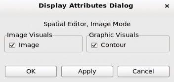
- The font size can range from zero to four.
- The size identifies the font (TextFont0 to TextFont4) to use for the writing of the text to the display.
- This variable can be overridden to increase/decrease the font size of the contour labels of scalar and vector weather elements when the graphic visuals contour is turned on.
- Contour Tool Line Labeling Font (Cline_font)
- The contour tool line labeling font variable (an example is shown below) changes the size of the contour tool line labels.
- The font size can range from zero to four.
- The size identifies the font (TextFont0 to TextFont4) to use for the writing of the text to the display.
- This variable can be overridden to increase/decrease the font size of the contour tool line labels.

- History Mode
- The history mode will show the origin, source, and modified state of all of the grids using a series of colors and patterns.
- Generally colors are used to indicate model source or grid origin and patterns are used to indicate that the grid has been modified.
- History Model/Origin Color (HistoryModel/OriginColor)
- The basic color algorithm is:
- If the origin of the grid came from a model:
- Then the software looks for a configurable item (history model color) denoting a color for that particular model (examples are shown below). If found, the grid block is painted that color.
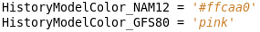
- If the particular configuration item is not found for the model, then the color specified in history origin color populated (an example is shown below) is used.
- If not defined, a gray color is used.

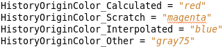
- If the origin of the grid did not come from a model:
- Then the color of the grid block is the color specified in history origin color origin type (examples are shown below).
- History User Mod Pattern Me/Other (HistoryUserModPattern_Me/Other)
- The basic pattern algorithm is:
- If the grid has not been modified, then no fill pattern is used and the grid block is solid.
- If the grid has been modified by you, then the fill pattern will be that specified by history user mod pattern me (an example is shown below).

- If the grid has been modified by someone else, then the fill pattern will be that specified by history user mod pattern other (an example is shown below).

- History User Mod Text Me/Other (HistoryUserModText_Me/Other)
- The text characters modified algorithm is:
- If the grid has been modified by you, then text contained in history user mod text me (an example is shown below) is used.

- If the grid has been modified by someone else, then the text contained in history user mod text other (an example is shown below) is used.

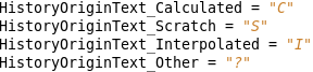
- History Model/Origin Text (HistoryModel/OriginText)
- The text characters origin and model algorithm is:
- If a grid has not been modified and has originated from a model:
- If a model-specific text string is provided, as a configuration item in the form of history model text model name (an example is shown below), then those will be the characters used.

- If a model-specific text string is not provided, then the configuration item history origin text populated (an example is shown below) is used to define the text string.

- If a grid has not been modified, and its origin is not a model, then the configuration item of history origin text origin type (examples are shown below) is used to define the text string.
- The color and text associated with populated grids may be tailored for each model source.
- The colors may be specified as a known color available in GFE or as a '#rrggbb' color.
- The available fill patterns are WHOLE, WIDE, SCATTERED, WIDE_SCATTERED, ISOLATED, TRANS_25PC_45DEG, TRANS_25PC_135DEG, SELECTED_AREA, OCNL, LKLY, DUALCURVE, CURVE, VERTICAL, CROSS, HORIZONTAL, and BIGCROSS.
- These variables can be overridden to change various aspects of the Grid Manager History mode.
- Pencil Tool Width (parmName_pencilWidth)
- The pencil tool width variable (an example is show below) defines the pencil tool's width on a per weather element basis, in grid cells.
- If not specified, the value defaults to four grid cells.
- Changing the pencil tool's width allows the pencil tool to change more/fewer grid cells when using it on a certain weather element grid.

- Pencil Tool's Influence (PencilToolInfluence_list)
- The pencil tool's influence variable (an example is shown below) defines the pencil tool sizes that appear on the Pencil Tool Influence menu (shown below) on the Spatial Editor right-click and hold popup menu.
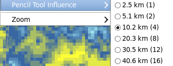
- You can enter as many sizes as you want, but the resulting menu may be too long to be completely displayed on the screen.
- This variable can be overridden to increase/decrease the number of pencil tool influence sizes and the sizes themselves can be changed.

- Interpolation Algorithm (parmName_interpolateAlgorithm)
- The interpolation algorithm variable (an example is shown below) defines the interpolation algorithm, for a weather element, that is used when grid interpolation is performed.
- The available options, which must be quoted, are: "CUBIC_ADVECT", "LINEAR_ADVECT", "CUBIC_NOADVECT", and "LINEAR_NOADVECT".
- The CUBIC_ADVECT algorithm applies cubic spline to the data points temporally.
- The algorithm looks for areas that can be advected.
- The advection component of the algorithm, works best for weather elements that contain areas of zero value.
- The CUBIC_NOADVECT algorithm applies cubic spline to the data points temporally.
- The software gradually adjusts points from starting value to ending value without advection considerations.
- The LINEAR_ADVECT algorithm applies linear calculations to adjacent base grids temporally.
- The software looks for areas that can be advected.
- The advection component of the algorithm works best for weather elements that contain areas of zero value.
- The LINEAR_NOADVECT algorithm applies linear calculations to adjacent base grids temporally.
- The software gradually adjusts points from starting value to ending value without advection considerations.
- By default, most weather elements use CUBIC_NOADVECT, except for Wx, PoP, Sky, and QPF which use CUBIC_ADVECT.
- Wind and Wx cannot be changed.
- The interpolation algorithms must be specified in all caps.
- This variable can be overridden for all weather elements except for weather and wind to specify the algorithm that is used when grid interpolation is performed on that particular weather element's grids.

- Set Value Zoom (SetValue_zoom/parmName_SetValue_zoom)
- The set value zoom variable (an example is shown below) defines the zoom factor for the pickup value dialog to use for all weather elements if they aren't explicitly defined by the weather element.
- The pickup value dialog is used to enter values for use in the assign value Smart Tool.
- This dialog was previously called set value.
- The pickup value dialog has the ability of a one-level zoom factor.
- Left-clicking on the dialog will zoom in or out one level, i.e., either the entire parameter range is seen or the zoomed in range is seen.
- A value of 4 indicates one quarter of the element's maximum range will be displayed when the dialog is zoomed in.
- For example if the temperature bounds are -30 to 130 degrees which is a range of 160 degrees, and the zoom factor is 4, then the dialog will show a 40 degree range when zoomed in.
- Individual weather elements can specify different zoom factors (an example is shown below).
- These variables can be overridden for a specific weather element or all weather elements to specify the zoom factor on the pickup value when zooming in one-level.

- Line Width (parmName_lineWidth)
- The line width variable (an example is shown below) defines the line width of a weather element.
- A weather element's line width is used to draw their graphics on the Spatial Editor.
- The larger the number the wider the line.
- Do not include a decimal point after the number.
- Valid numbers are zero and up.
- This variable can be overridden for any weather element to increase the line width for bounded area outlines, contour lines, and wind barb and wind arrow lines.
- Font Offset (parmName_fontOffset)
- The font offset variable (called magnification on the GFE menus and an example is shown below) allows the default font offset to be increased or decreased on a per-parameter basis for all weather elements.
- The value usually ranges from -2 to 3.
- If you specify a value outside of that range, it will increase/decrease the font offset but it is not recommended.
- This variable can be overridden for any weather element to increase/decrease the font offset (magnification) for bounded area outlines, contour lines, and wind barb and wind arrow lines.
- Density (parmName_Density)
- The density variable (an example is shown below) controls the packing of wind barbs and arrows for the vector Spatial Editor displays and the packing of contour intervals for the scalar Spatial Editor displays.
- Typical values range from -2 to 2.
- You can use values outside of this range.
- Do not include a decimal point after the number.
- This variable can be overridden for any scalar or vector weather element to increase the density of wind arrows and wind barbs for vector weather elements and the packing of contours for scalar weather elements.
- Temporal Editor Data Pane Size (parmName_temporalDataPaneSize)
- The temporal editor data pane size variable (an example is shown below) allows the user to control the initial size of the temporal editor pane(s) based on the weather element first loaded into a pane.
- If not specified, the default is 150 pixels in height.
- Do not include a decimal point after the number.
- This variable can be overridden for any weather element to increase/decrease the initial (vertical) size of the Temporal Editor pane(s).

- Contour Interval (parmName_contourInterval) and Values (parmName_contourValues)
- Contour intervals and values both specify the contour values for a given parameter.
- There are two ways to define contour values, either by specifying a complete set of values (an example is shown below), or by specifying a single interval (an example is shown below).
- If both methods are defined, then the contour values will be used, overriding the defined contour interval.
- Be sure to include decimal points after the number(s).
- These variables can be overridden for any weather element to setup either a different contour interval or to specify specific contour values.


- Delta Value (parmName_deltaValue)
- The delta value variable (an example is shown below) defines the default delta (adjust up, adjust down) value used for the adjust Smart Tools.
- Be sure to include decimal points after the number.
- If not defined, it defaults to the minimum precision.
- For example, a precision of 0 indicates a delta of 1 and a precision of 1 indicates a delta of 0.1.
- This variable can be overridden for any weather element to specify a value to be used with the adjust Smart Tools.
- Fuzz Value (parmname_fuzzValue)
- The fuzz value variable (an example is shown below) defines the value considered to be the same using the select homogenous area (shown below) on the right-click and hold Spatial Editor menu.

- Fuzz values are used to determine all grid points that are contiguous and close to the selected point to set a new edit area.
- For example, if the fuzz value is 2.0 degrees for temperature and you click on a point that is 40 degrees then all points between 38 and 42 degrees that are contiguous to that point will be selected.
- If not defined, it defaults to 1/100 of the parameter's range.
- Be sure to include a decimal point after the number.
- This variable can be overridden for any weather element to specify a value to be used for the select homogenous area function on the Spatial Editor right-click and hold menu.
- Wind Format (WindFormat and parmName_windFormat)
- The wind format variable (an example is shown below) defines the default sample format for vector weather elements.
- The four possible formats are "ddff", "8pt", "16pt", and "d/f".
- If not specified, then the format is "ddff".
- The format affects the samples on the Spatial and Temporal Editors, the color bar pick-up values on the Spatial Editor, and the set value dialog for vector weather elements.
- The user may specify a format for all vector elements or can specify the format for a particular vector weather element (an example is shown below).
- These variables can be overridden for all vector weather elements or a specific vector weather element to select the default format.

- Default Value (parmName_defaultValue)
- The default value variable (an example is shown below) defines the default values which are used for creating a grid from scratch, for scalar, vector, weather, and discrete weather elements and may be specified on a per weather element basis.
- By default, scalar has the weather element's minimum value, vector has a magnitude and direction of 0, weather has <noWx>, and discrete has the first defined discrete key.
- Be sure to specify the correct format for the particular weather element.
- This variable can be overridden for any weather element to specify the value that is used for creating a grid from scratch.

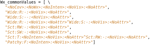
- Weather Common Values (Wx_commonValues)
- The weather common values variable (an example is shown below) defines the common types that appear on the Temporal Editor popup and the Spatial Editor color bar popup menus.
- The format is the "ugly" string of a Weather Key.
- The general format of a weather key consists of one or more subkeys separated by a caret ('^').
- The subkey consists of five parts: coverage/probability, weather type, intensity, visibility, and optional attributes.
- Each of these sections is separated by a colon.
- The optional attributes, if any are separated by commas.
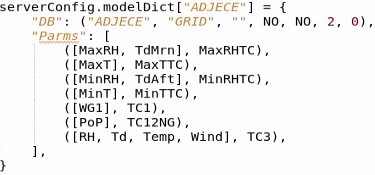
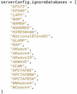
- The weather key must consist of valid coverages/probabilities, weather types, intensities, visibilities, and optional attributes as defined in serverConfig.py.
- This variable can be overridden to specify which weather keys appear on the Temporal Editor popup and Spatial Editor color bar popup menus.
- Discrete Common Values Definitions (parmName_commonValues)
- The discrete common values variable defines the common types that appear on the Temporal Editor popup and the Spatial Editor color bar popup menus.
- The format is the key string of the discrete key.
- Discrete keys are simpler than weather keys in that they are represented by strings.
- Multiple keys are separated by a caret ('^').
- This variable can be overridden for any discrete weather element to specify which discrete keys appear on the Temporal Editor popup and Spatial Editor color bar popup menus.
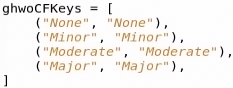
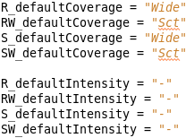
- Weather Dialog Default Values (weatherType_defaultCoverage/Intensity)
- The weather dialog default value variables (an example is shown below) define default intensity and coverage/probability values that will be displayed on the weather set value (pickup value) dialog when creating a new weather key.
- The format is the weather type followed by the keyword.
- The coverage(s) and intensity (ies) must be valid as defined in serverConfig.py.
- These variables can be overridden for any weather type to specify the default coverage and/or intensity that appear on the pickup value dialog when creating a new weather key.
- Default Color Table Entries (parmName_defaultColorTable)
- The default color table variables (an example is shown below) define the initial color table to use for a particular weather element.
- The name of the color table (color map) should match the name of a color map that is located in the Localization Perspective under the CAVE Folder under the Color Maps Folder.
- These variables can be overridden for any vector or scalar weather element to specify the color table that is used when loading that particular weather element.

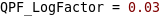
- Logarithmic Color Tables (parmName_LogFactor)
- The logarithmic color table variable (an example is shown below) defines a color table that assigns color slots to values logarithmically, rather than the normal case of linearly.
- The value given must be greater than zero.
- The closer the value is to zero, the steeper the log curve will appear.
- Values greater than one will result in an almost linear assignment of the values near the weather element's minimum possible value.
- For some scalar weather elements (e.g., QPF) due to the normal range of values it makes sense to have a logarithmic color table as opposed to a linear color table to easily see all of the values.
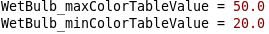
- Max and Min Color Table Values (parmName_max/minColorTableValue)
- The max and min color table value variables (an example is shown below) define the initial range of color tables.
- By default, all color tables (except for WEATHER) are spread out over the range of the minimum to maximum weather element possible value.
- Be sure to specify the correct format for the particular weather element.
- These variables can be overridden for any weather element to specify the max and min value for the color table for that weather element.
- Automatic Fit to Data Color Tables (parmName_fitToDataColorTable)
- The automatic fit to data color table variables (an example is shown below) specify that the initial color table is to be calculated based on the fit to data algorithm.
- This parameter overrides any specified max/min color table values.
- There are several algorithms available: "None", "All Grids", "Single Grid", "All Grids over Area", and "Single Grid over Area".
- The Single Grid options are not available for GFE and only apply to the ifpImage program.
- The area used is the current edit area for GFE.
- This variable can be overridden for any weather element to create the color table for that weather element based on the fit to data algorithm that is specified.

- Color Bar Labels (parmName_ColorBarLabels)
- The color bar labels variable (an example is shown below) defines the desired labels on the Spatial Editor color bar on a per weather element basis.
- The values need to be entered as floats (with a decimal point).
- This variable can be overridden for any scalar or vector weather element to specify the color bar labels for that weather element on the Spatial Editor color bar.

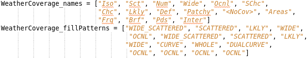
- Weather Coverage Names and Fill Patterns (WeatherCoverage_names/fillPatterns)
- The weather coverage names and fill patterns variables (an example is shown below) define the fill pattern used for a particular weather coverage or probability.
- These variables are parallel lists.
- For example, if “Iso” coverage is in the 1st entry of the list and ISOLATED appears in the first entry of the fill patterns, then for Iso coverage, the fill pattern ISOLATED will be used.
- The available fill patterns are WHOLE, WIDE, SCATTERED, WIDE_SCATTERED, ISOLATED, TRANS_25PC_45DEG, TRANS_25PC_135DEG, SELECTED_AREA, OCNL, LKLY, DUALCURVE, CURVE, VERTICAL, CROSS, HORIZONTAL, and BIGCROSS.
- The weather coverage names must be valid coverages/probabilities as defined in serverConfig.py.
- These variables can be overridden to specify the weather coverage names and their corresponding fill patterns.
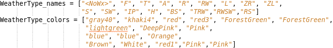
- Weather Type Entries (WeatherType_names/colors)
- The weather type names and colors variables (an example is shown below) define the color used for a particular weather type(s).
- Weather type entries are generic entries without intensities.
- These variables are parallel lists.
- The weather color table algorithm, looks at the weather type or combination of types, as listed in the names list, and matches the list with the specified color.
- For example, if T appears in the names as the first entry and brown2 appears in the colors list for the first entry, then for weather type T, the color shown will be brown2.
- These two lists are searched after the Weather Type Inten names and colors lists.
- The colors may be specified as a known color available in GFE or as a '#rrggbb' color.
- The weather type names must be a valid (combination of) weather type(s) as defined in serverConfig.py.
- These variables can be overridden to specify the weather type or combination of weather type names and their corresponding colors.
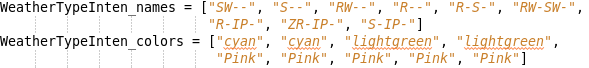
- Weather Type Intensity Entries (WeatherTypeInten_names/colors)
- The weather type inten names and colors variables (an example is shown below) define the color used for a particular weather type(s) and intensity(ies) combination.
- Weather type intensity entries are parallel lists of names of colors.
- Weather type intensity entries are specific entries that contain intensities.
- The weather color algorithm looks first at these lists to find a specific type/intensity match.
- The colors may be specified as a known color available in GFE or as a '#rrggbb' color.
- The weather type inten names must be a valid (combination of) weather type(s) and intensity(ies) as defined in serverConfig.py.
- These variables can be overridden to specify the weather inten type or combination of weather inten type names and their corresponding colors.
- Weather Generic Colors (WeatherGeneric_colors)
- The weather generic colors variable (an example is shown below) defines the colors for any weather types that are not defined in the weather type names or weather type inten names lists.
- The set of generic colors are also used for complex weather patterns where three or more different probabilities/coverages are present in a grid cell.
- The colors in this list will be used before a "random" color is chosen.
- The colors may be specified as a known color available in GFE or as a '#rrggbb' color.
- This variable can be overridden to specify the colors for weather that isn't specified in the weather type inten names or weather type names lists.

- Missing Data Mode (MissingDataMode)
- The missing data mode variable (an example is shown below) defines the default setting for missing data mode.
- Possible values are:
- Stop: Stop execution of a Smart Tool if there is missing data
- Skip: Skip grids for which there is missing data (A User Alert message will report which grids were skipped.)
- Create: Create grids to supply the missing data (A User Alert message will report which grids were created.).
- This variable can be overridden to set the initial setting of missing data mode.

- Show Time Range Warning (ShowTimeRangeWarning)
- The show time range warning variable (an example is shown below) defines the default setting for showing a dialog box when the user attempts to edit grids when a selection time range is active.
- Acceptable entries are yes or no.
- This warning occurs so that users don't accidentally modify multiple grids.
- This variable can be overridden to set the initial setting of the time range warning.

- Show Empty Edit Area Warning (ShowEmptyEditAreaWarning)
- The show empty edit area warning variable (an example is shown below) defines the default setting for showing a dialog box when the user attempts to edit grids without an edit area being set.
- Acceptable entries are yes or no.
- This variable can be overridden to set the initial setting of the empty edit area warning.

- Select Grids When Time Stepping (SelectGridsWhenStepping)
- The select grids when time stepping variable (an example is shown below) specifies whether the selection time range will track the Spatial Editor time when time stepping.
- Time stepping is accomplished using the tool bar step forward and back buttons or keyboard shortcuts (if your office has them defined/enabled).
- When this preference is enabled (i.e., yes), the selection time will be set to:
- the one hour period surrounding the spatial time, if there is no active weather element
- or the time constraint box for the active weather, if there is no grid that intersects the spatial editor time
- or the valid time of the grid for the active weather element that intersects the spatial editor time
- In addition when this preference is enabled, all weather elements except the active weather element will be deselected.
- When this preference is disabled (i.e., no), the selection time range and the set of selected weather elements will not change when using the GFE tool bar stepping buttons or keyboard shortcuts.
- Acceptable entries are yes or no.
- This variable can be overridden to set the initial setting of selecting grids when time stepping is performed.

- Time Scale Periods
- The time scale periods variable (an example is shown below) defines the list of named selection time ranges that appear on the time scale (the box above the weather element(s) in the Grid Manager and Temporal Editor).
- The time periods must be put in single quotes on the list.
- This variable can be overridden to specify any number of time scale periods that appear on the time scale above the Grid Manager and Temporal Editor.

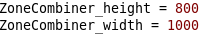
- Zone Combiner Variables (ZoneCombiner_height/width)
- The zone combiner height and width variables (an example is shown below) define the height and width of the zone combiner (Formatter Launcher).
- These variables allow you to increase/decrease the size and shape of the Formatter Launcher.
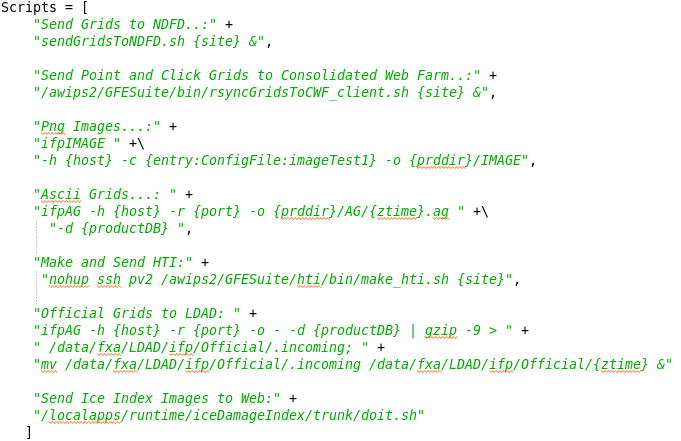
- Scripts List
- The scripts list variable (an example is shown below) defines the product generation scripts that show up in the Product Generation Script GUI that is available under the Products Menu by clicking Scripts... .
- This list is where sites can declare their own local scripts.
- It is expected that sites will override the product generation scripts using a SITE-level GFE configuration override.
- At some sites the recommended practice is to use scripts.append to add a script to the baseline scripts list as opposed to overwriting the whole baseline scripts list.
- Scripts are discussed in more detail in the Scripts section.
Map Issues
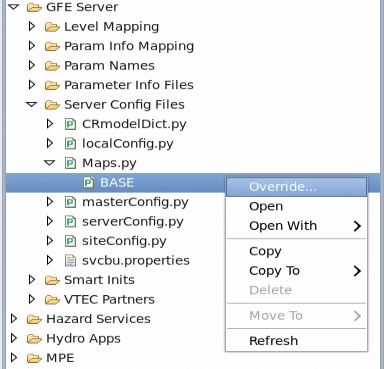
Maps are CAVE Map Bundles. You can load them in GFE, but cannot change their appearance in GFE. If you want to change the appearance of a map (e.g., States), go to the Localization Perspective under the CAVE Folder, under the Bundles Folder, under the maps Folder, and find the name of the map that you want to change (e.g., States). Making a change to the map will change its appearance in GFE and D2D. The location of the maps Folder is shown below. 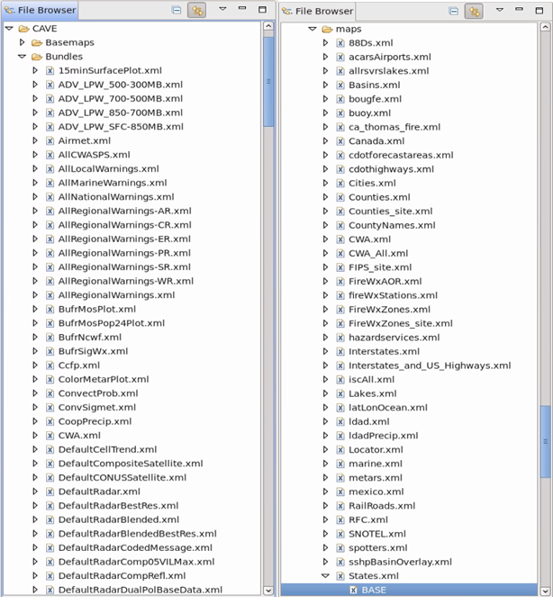
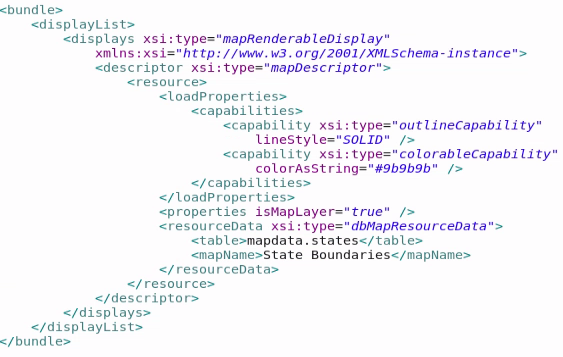
Next, in order to make changes to a BASE-level map you will first need to copy the file to SITE by right-clicking on BASE, then selecting Copy To, then selecting SITE (XXX) where XXX is your site id. Next you can open the SITE-level file and make the changes (overrides) that you want. As an example, two items that could be changed with the States Map is the line pattern or color. To change the line pattern, change the lineStyle from SOLID to DASHED. To change the color, change the colorAsString from #9b9b9b to some other hex code or the name of a color in GFE such as, blue.
The only map variable/parameter that can be changed/overridden in a SITE-level or USER-level GFE config file is MapBackgrounds_default, which was discussed above.
Scripts
The scripts entries define the contents of the Product Generation Scripts GUI which is available from the Products Menu. Each script entry is a text string of the form "<Entry Name>:" + "<command line script>", where <Entry Name> will appear in the Product Generation Menu and <command line script> is the Linux command that will be run when the script is chosen. The following variables can be used in scripts and GFE will fill in the appropriate information before executing the script:
- {host} --server hostname
- {port} --server port
- {site} --site identifier
- {productDB} --product database -- this is the Official Database if it exists; otherwise, it's the Mutable (Fcst) Database
- {SEstart} --Start of Spatial Editor time: format of all times: YYYYMMDD_HHDD
- {SEend} --Spatial Editor time plus one second
- {SelectedStart} --Start of Selected Time range
- {SelectedEnd} --End of Selected Time range
- {time} --Current local time in format: YYYYMMDD_HHMM
- {ztime} -- Current Zulu Time in format: YYYYMMDD_HHMM
- {module:<module name>} --The correct path of the module will be substituted in the command line. The module must have a .py extension.
- {home} --Substitutes the home GFESuite directory at runtime (may differ from local to server)
- {prddir} --Substitutes the product directory at runtime (may differ from local to server)
Note that the directory {} values should be used, rather than hard-coding them, if you want to be able to run a process locally as well as remotely. If the following variables are used in a script, a dialog will appear for the user to make a selection from a simple GUI before the script is executed:
- {parmsMutable} those listed in the Forecast Database
- {refset}
- {maps}
- {database}
- {outputfile}
- {output directory}
- {startTime}
- {endTime}
To have the user prompted for a named variable, use the following in your script: {entry: <name of variable>: <default value>}. To have the user prompted for a list of radio button variables, use {entryButtons: <name of variable>: <list of values separated by commas>}. To have the user prompted for a list of check button variables, use {entryChecks: <name of variable>: <list of values separated by commas>}. If the name of the entryButtons or entryChecks is "EditAreas", the system will accept edit area or edit area group names. The system will check for groups and will automatically expand them to the areas. To string multiple command line arguments together, use the following format for your command line script: "csh -c (<command line 1>; <command line 2>; command line 3>)".
For IdM Phase 2 sites, when running any script that uses xterm (e.g., Make and Send HTI), xterm - e MUST be replaced with nohup. When running those scripts, the user's CAC needs to be removed from the keyboard.
Baseline scripts
The Baseline scripts are shown below and are defined in the Scripts list in gfeConfig.py.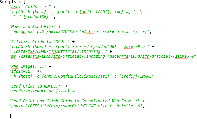
Task: Configuring What Goes to NDFD and Web
This task demonstrates how to configure what goes to NDFD and Web.
View Jobsheet
Task: Adding Local Scripts
This task demonstrates to add local scripts to the SITE-level GFE config file.
View Jobsheet
Color Maps
Color maps are CAVE Bundles like maps. They are located in the Localization Perspective under the CAVE Folder under the Bundles Folder in the Color Maps Folder.
Task: Color Maps
This task demonstrates how to create Color Maps and shows where to put them.
View Jobsheet
Cleanup
Make sure that you only have one SITE-level GFE config file. Make sure that there are not duplicate lines of code (duplicate overrides) or any typos in your file. Make sure that all of your overrides are used in changing your GFE configuration in some way. Make sure that the value(s) used to override a parameter are not identical to the value(s) in gfeConfig.py. Make sure every parameter that is in your file also exists in gfeConfig.py. Make sure that there are not any ifpImage only parameters in your file. Remove all AWIPS1 remnants from your file. Remove the Toggle HorizVert keyboard shortcut.
Structure
Smart Tools contain a tool type variable (shown below) which is normally set to numeric.

Smart Tools contain a weather element edited variable (shown below) which can be set to variableElement or a specific weather element. It is needed for the Smart Tool to show up in the right-click and hold popup menu and the Edit Actions dialog. If it is set to NONE, then the Smart Tool won't appear in the right-click and hold popup menu or the Edit Actions dialog.

Smart Tools contain a screen list list (shown below) which determines the weather elements that the Smart Tool appears for in the right-click and hold popup menu and the Edit Actions dialog. It can be a type, types of, or a specific weather element. If this is set to "", then the Smart Tool won't appear in the right-click and hold popup menu or the Edit Actions dialog.

Smart Tools can also contain a hide tool variable. In order to hide the tool from the right-click and hold popup menu or the Edit Actions dialog, the hide tool variable (shown below) can be set to any integer not zero. It is usually just set to zero or one.
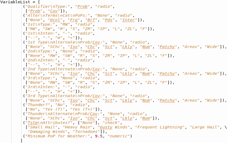
Smart Tools can declare a variable list list (shown below) which solicits variables/values for certain parameters from the user. It must appear before or after the Tool Class and not within it. The variable list list contains a list of tuples defining each variable and resides in the Python file for the Smart Tool. The variable tuple in the variable list is in the form: ("Variable", default value, variable type, optional list). Variables for the variable list list can be of the following types:
- "numeric" -- will ensure the user enters a number.
- "alphaNumeric" -- will accept any character and will automatically convert the string to a number if possible.
- "radio" -- a set of radio buttons i.e., one and only one choice must be made by the user among a list of values. In this case a list of values must be supplied.
- "check" -- a set of check buttons, i.e., the user may select zero or more values from a list. In this case a list of values must be supplied and the default value to be checked "on" initially. The return value for such a variable in var dict is a list of values that were checked "on" when the user selected "Ok".
- "scale" -- a slider-bar type scale. In this case a list containing the minimum and maximum values must be supplied along with the default value. A resolution can also be specified if desired. The default is one.
- "model" -- gives a list of GFE surface model runs (e.g., NAM12, GFS40, RUC80).
- "D2D_model" -- gives a list of D2D model runs (e.g., NAM12, GFS40, RUC80).
- "label" -- simply displays text given in the "Variable" slot.
- "scrollbar" -- adds a scrollbar to the variable list dialog. This is intended for dialogs that have become too large for the screen. A desired height for the dialog must be given. For example: ("",500, "scrollbar") will add a scrollbar to the dialog and set the dialog height to 500 pixels. Only one scrollbar entry is processed per variable list dialog.
Smart Tools can declare a model list variable (shown below) which contains the models available at a WFO.

They can declare a locations list variable which is a list of tuples consisting of various locations with their latitude and longitude coordinates that are used by the Smart Tool. The next portion of the structure is where the import statements begin. Smart Tools import numpy. They import SmartScript due to there being many methods/functions that can be called that are in SmartScript.py. Smart Tools can contain other import statements as needed.
Smart Tools contain a Class Tool which inherits SmartScript.SmartScript. This class contains a __init__ method. The Tool class contains an execute method which may have weather element arguments plus various special arguments which will be supplied by the system when it is called. The class contains other methods as needed. These other methods can contain the additional argument ToolTimeRange. One of the methods that are sometimes used is preProcessTool which is called once at the beginning of the tool, cannot have weather element or grid arguments, and is reserved for point-based tools. Another method that is sometimes used is postProcessTool, which is called once at the end of the Smart Tool, cannot have weather element or grid arguments, and is reserved for point-based tools. One method that is sometimes used is called preProcessGrid which is called once at the beginning of each grid and can have grid arguments but not point arguments. Additionally, the Smart Tool logic can be put in this method and then pass is put in the execute method. Another method that is sometimes used is called postProcessGrid which is called once at the end of each grid and can have grid arguments but not point arguments.
Description and When to Use vs. Procedure
Smart Tools are bits of code that perform operations on a grid-by-grid basis. They appear under the E on the Button Bar (toolbar, shown below) and the right-click and hold popup menu on the spatial editor. Smart Tools are Edit Actions that you create.
These tools allow you to write an equation that modifies forecast grids in a meteorologically consist way. When execution of the tool goes into the execute method, the grid is (or grids are) marked as edited. "Self" refers to a particular Tool's class instance. Make sure to list "self" as the first argument of method definitions (e.g., def myMethod(self, arg1, arg2)). When calling methods you create in the Tool class, use self._methodName omitting self as the first argument (e.g., X = self._myMethod(arg1, arg2)). Call self.abort(errorString) to stop execution of the tool and display a message to the user. Call the self.noData(messageString) to stop execution of the tool and return a "NoData" error which can be checked by a Procedure.
User defined Smart Tool methods and variables, which need to span multiple methods are preceded by an underscore (e.g., self._modifyValue and def_myMethod). Smart Script Library and other Utility methods do not have a preceding underscore (e.g., self.getGrids). The Smart Script Library is a set of convenient library functions available to simplify the jobs of the tools. Through it, Smart Tools access data, create soundings, and perform unit conversions. The reserved methods (e.g., execute and preProcessTool) do not have a preceding underscore.
If a weather element other than the one that is being edited is requested, it is possible that the system will encounter multiple corresponding grids. For example if a six-hour QPF grid is being edited, there may be multiple Wind grids that fall within the time range. In this case the system will automatically return the time-weighted average of the grids. This means that the value in the three-hour wind grid will be weighted three times more heavily than those in a one-hour grid when calculating the average value. A time-weighted average for a weather-type element is defined as the combination of all weather values encountered.
Some Smart Tools are specifically designed to be run by a Procedure. Smart Tools should be used to perform simple operations on a grid-by-grid basis on a single field as opposed to using a Procedure.
Good Examples
- Adjust
- ApparentTemperature
- CarSnowAmt
- EnufCloudForPoP
- getSumGrids
- HeatIndexTool
- LimitValues
- MakeTmpGrid
- Populate_SkyTool
- QPF_SmartTool
- RemoveWx
- Show_ISC_Highlights
- WindGustFromAlgorithm
Task: Smart Tools
This task demonstrates how to execute, create, and modify Smart Tools.
View Jobsheet
Procedures
Structure
Procedures begin in a similar way to Smart Tools, with a Class Procedure instead of Tool and the same methods from the Smart Script Library are available. They can declare a menu items variable (shown below) which defines the GFE menu item(s) where the procedure will appear.

They can declare a supported elements variable (shown below) which is analogous to the weather element edited variable for Smart Tools except that the supported elements variable is a list. This variable specifies the weather elements that the Procedure can be run on.

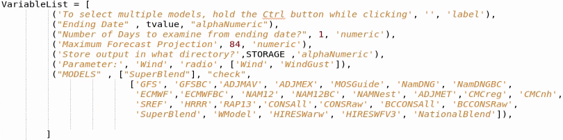
Procedures can declare a variable list list (shown below) which solicits variables/values for certain parameters from the user. It must appear before or after the Procedure Class and not within it. The variable list list contains a list of tuples defining each variable and resides in the Python file for the Procedure. The variable tuple in the variable list is in the form: ("Variable", default value, variable type, optional list). Variables for the variable list list can be of the following types:
- "numeric" -- will ensure the user enters a number.
- "alphaNumeric" -- will accept any character and will automatically convert the string to a number if possible.
- "radio" -- a set of radio buttons i.e., one and only one choice must be made by the user among a list of values. In this case a list of values must be supplied.
- "check" -- a set of check buttons, i.e., the user may select zero or more values from a list. In this case a list of values must be supplied and the default values to be checked "on" initially. The return value for such a variable in var dict is a list of values that were checked "on" when the user selected "Ok".
- "scale" -- a slider-bar type scale. In this case a list containing the minimum and maximum values must be supplied along with the default value. A resolution can also be specified if desired. The default is one.
- "model" -- gives a list of GFE surface model runs (e.g., NAM12, GFS40, RUC80).
- "D2D_model" -- gives a list of D2D model runs (e.g., NAM12, GFS40, RUC80).
- "label" -- simply displays text given in the "Variable" slot.
- "scrollbar" -- adds a scrollbar to the variable list dialog. This is intended for dialogs that have become too large for the screen. A desired height for the dialog must be given. For example: ("",500, "scrollbar") will add a scrollbar to the dialog and set the dialog height to 500 pixels. Only one scrollbar entry is processed per variable list dialog.
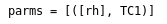
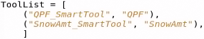
Procedures can declare a tool list variable (shown below). This is recommended if Smart Tools are being called in the procedure. It can be used to show which grids will be modified by the Procedure. The tool list variable consists of a list of tuples containing the name of the Smart Tool and the weather element to be edited which can be a specific weather element or variableElement.
Procedures can declare a model list variable (shown below) which contains the models available at a WFO.

They can declare a dialog names variable, which holds all the names that are added to the dialog. Procedures can declare an available element groups variable (shown below), which controls the weather element groups available.

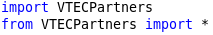
The next portion of the structure is where the import statements begin. Procedures import numpy. They import SmartScript due to there being many methods/functions that can be called that are in SmartScript.py. Sometimes Procedures contain a different class to import, such as TropicalUtility, GridManipulation, or ModelBlendutility. Procedures can contain other import statements as needed.
Procedures contain a Class Procedure which inherits SmartScript.SmartScript, GridManipulation.GridManipulation, ModelBlendUtility.ModelBlendUtility, or some combination of them, or inherits TropicalUtility.TropicalUtility. This class contains a __init__ method. The Procedure class contains an execute method which may have weather element arguments plus various special arguments which will be supplied by the system when it is called. The class contains other methods as needed.
Procedures are bits of code which can perform operations on many grids and may call Smart Tools and other useful commands which can create, interpolate, and delete grids. They have the capability of internally defining the grids and time range upon which they operate. Procedures themselves can call other Procedures. They can be configured to appear under various menu items on the GFE Main Menu and can take several minutes to complete. Procedures can be run in the background from the command line using runProcedure which is discussed in the Command Line Scripts section. The goal of a Procedure is to execute related tools together in succession and perform operations such as copying, creating, and interpolating grids. Procedures are a sequence of commands which modify the forecast database.
Procedures operate at a higher level through the Smart Script Library. "Self" refers to a particular Procedure's class instance. Make sure to list "self" as the first argument of method definitions (e.g., def myMethod(self, arg1, arg2)). When calling methods you create in the Procedure class, use self._methodName omitting self as the first argument (e.g., X = self._myMethod(arg1, arg2)). Call self.abort(errorString) to stop execution of the Procedure and display a message to the user. Call the self.noData(messageString) to stop execution of the Procedure and return a "NoData" error which can be checked by a Procedure.
User defined Procedure methods and variables, which need to span multiple methods are preceded by an underscore (e.g., self._modifyValue and def_myMethod). Smart Script Library and Utility methods do not have a preceding underscore (e.g., self.getGrids). The Smart Script Library is a set of convenient library functions available to simplify the jobs of the Procedure. The reserved methods (e.g., execute) do not have a preceding underscore.
A Procedure should be used when it is desired to do more (complex operations) than a single Smart Tool can. They should be used to execute related tools in succession. Procedures should be used to perform operations such as copying, creating, and interpolating grids. They should be used to call Smart Tools and other Procedures. Procedures should be used for TimeShift desired tools. They should be used to create grids from scratch and assign the default value to a set of grids. Procedures should also be used to remove grids from the forecast.
Good Examples
- Align_Grids
- BOIVerify
- CheckTTdWind
- DiffFromClimo
- Extrapolate
- FinalizeHazards
- HazardRecovery
- ISC_Discrepancies
- MakeHazard
- NDFDgridCheck
- PopulateFromClimo
- QPF_SnowAmt
- RevertTopo
- SendProposedToWFO
- StormInfo
- TCTornadoThreat
- UpdateForISCWithoutChange
- ViewWCL
Task: Procedures
This task demonstrates how to execute, create, and modify Procedures.
View Jobsheet
Text Formatters
For more information, a GFE Text Formatters presentation is linked here.
The CONFIGURED-level files are generated by EDEX from templates which are located in ../common_static/base/gfe/textproducts/templates. These templates are only updated with AWIPS builds. Many local definition settings are automatically setup when these files are created. Almost all baseline text formatters exist as CONFIGURED-level files. CONFIGURED-level files are regenerated automatically if EDEX is restarted or the GFE Site is deactivated/activated. CONFIGURED-level files are created by ../common_static/base/gfe/textproducts/preferences/configureTextProducts.py. The script contains a list of possible PILs which are compared against the site's afos2awips.txt file to determine what gets generated. It is very important to keep your site's afos2awips.txt file up to date on dv3/dv4/dv5. Sites should have a link from /awips/fxa/data/afos2awips.txt to /data/fxa/afos2awips.txt. You can get configureTextProducts.py to run by restarting EDEX (requires ESA, ITO, or a call to NCF), GFE Site Activation (deactivated/activated), or by manually running via terminal on dv3, dv4, or dv5 /awips2/GFESuite/bin/configureTextProducts XXX where XXX is your site id. The CONFIGURED-level files can be overridden via subclassing.
Task: How to Update (Configure) TextProducts
This task demonstrates how to update (configure) TextProducts.
View Jobsheet
Inheritance
Text Products have access to Library Methods through inheritance. When a class, called the "derived class", inherits from another class (the bass class) it means that all the methods available in the base class are also available to be used in the derived class. If the derived class wants to replace or override a method in the base class it simply has to define a method with the same name. The Text Infrastructure consists of base classes and derived classes. All the Text Products are derived classes from base classes. All Text Products are derived from the TextRules and Analysis Classes. The TextRules class is derived from the Forecast Library Class. Local (SITE) Text Products are derived from Text Product Classes. The Text Products are CONFIGURED-level files and the Local Text Products are SITE-level files. The Forecast Library Class, TextRules Class, and Analysis Class should not be modified.
The Forecast Library Class contains general-purpose library methods for sampling the data, accessing edit areas, time ranges, and some simple formatting. The Analysis Class contains methods that create statistics given histograms sampled from the grids. The TextRules Class, in addition to all the Forecast Library methods, has many methods for formatting data given numeric values. Text Product classes inherit from the TextRules and Analysis classes which means they have access to methods from all three classes (i.e., Forecast Library, TextRules, and Analysis). Additionally, there are some classes (e.g., GenericHazards, AreaFcst) that inherit from the TextRules and Analysis classes and are inherited by (is a base class for) other Text Product classes. For example, GenericHazards is inherited by (a base class for) all the Hazard Text Products.
Configured files should not be changed by anyone. Most of the Text Products and Text Utilities files should be at the CONFIGURED-level. If a Text Product is at the CONFIGURED-level, then the Text Utilities for that Text Product will be at the CONFIGURED-level too but can have REGION- and/or SITE-level overrides. Region files also should not be changed and are the same for every office in the same region. REGION-level files override CONFIGURED-level files and SITE-level files override CONFIGURED- and REGION-level files. SITE-level files are used to make changes (overrides) to the Text Product Definitions and Overrides files in the Localization Perspective under the GFE Folder under the Text Utilities Folder.
Text Products
All Text Products contain a definitions section in a TextProduct Class with various other methods. They consist of CONFIGURED- and SITE-level files. Text Products can declare a variable list variable (an example is shown below), which solicits variables/values for certain parameters from the user, like Smart Tools and Procedures except the variable list variable is in the TextProduct class. For more information on the variable list variable see the Procedures or Smart Tools sections.

Overrides
When making overrides comment the lines you are changing. Only make overrides in the TTT_XXX_Overrides file for methods, definitions, or other parameters/variables (e.g., variableList) and TTT_XXX_Definitions for product definition settings where TTT is the three letter product name and XXX your site id. These files are located in the Localization Perspective under the GFE Folder under the Text Utilities Folder. You can override methods and certain portions of definitions in an Overrides file.
Naming Conventions
These common suffixes are used with thresholds and variables to indicate the type of value returned:
- _percentage - a number from 1-100
- _weight - a number from 0-1
- _threshold - typically a data value
- _dict - a Python dictionary
- _valueList - a Python list of phrase values
- _nlValue - non-linear values
TextRules and Analysis Class methods are called with self.methodname. Forecast Library and Standard Text Product Template methods are called with an underscore (eg., self._methodname). User-created text product methods and variables are called with a p and an underscore (e.g., self.p_methodname). This convention is followed for clarity and to insure that you do not inadvertently override an existing method or variable by giving your method or variable a duplicate name.
Troubleshooting Output and Logs
To troubleshoot Text Products, run locally and view error messages in the Process Monitor. Console logs are located in each user's caveData directory (/home/username/caveData/logs/consoleLogs/machinename). The Product Editor and Console Logs in this directory can help with diagnosing problems that occur when running the Formatter Launcher. EDEX logs are located in the /awips2/edex/logs directory on dv3/4/5. These logs are used for issues that occur when configureTextProducts.py is run.
Text Utilities
Text Utilities can only be imported into Text Products and cannot be run directly. They consist of BASE-, CONFIGURED-, and SITE-level files. Text Utilities contain many helper modules that form the foundation for all formatters. Most Regional and Site Overrides and Definitions files are Text Utilities. Text Utilities allow you to share methods between Text Products.
Definitions
A Definitions file contains a dictionary containing settings for a particular Text Product. The definition dictionary is initialized as a baseline formatter. Then they can be overwritten or added at the REGION- and/or SITE-Levels. Many settings are preset in the baseline formatter (by configureTextProducts) and do not need to be included at the SITE-level unless changes are needed. The safest way to retrieve a definition entry is by using getattr so a default value can be set in case the key does not exist (e.g., my Setting=getattr(self, "_lineLength, 66)).
What Goes Here vs. Overrides
Display name, Edit Area, Map Name for Combinations, product type, and product/header identifiers are included in Definition files. The database used for Text Products and other parameters used in the creation of Text Products are also included in Definition files.
Naming Conventions
These common suffixes are used with thresholds and variables to indicate the type of value returned:
- _percentage - a number from 1-100
- _weight - a number from 0-1
- _threshold - typically a data value
- _dict - a Python dictionary
- _valueList - a Python list of phrase values
- _nlValue - non-linear values
TextRules and Analysis class methods are called with self.methodname. Forecast Library and Standard Text Product Template methods are called with an underscore (e.g., self._methodname). User-created text utility methods and variables are called with a p and an underscore (e.g., self.p_methodname). This convention is followed for clarity and to insure that you do not inadvertently override an existing method or variable by giving your method or variable a duplicate name. Definitions files are named TTT_XXX_Definitions and Overrides files are named TTT_XXX_Overrides where TTT is the three letter product name and XXX is your site id.
Overrides
Use verbose comments to state where the override methods come from, or if it is a brand new method, and list the reason for the override, (e.g., def _determineTimeRanges(self, argDict) ZFP_GSP_Overrides of AreaFcst._determineTimeRanges. Modified to always sample snow accumulations for the 12 hours prior to the forecast product start time.) Consider using a debug_print method for the new/override method for use with Definition["debug"] in the SITE Definitions file (e.g., self.debug_print("\tZFP_GSP_Overrides version of AreaFcst._determineTimeRanges", 1)). Remember to check SITE overrides against changes in new formatter releases and baseline builds to see if the override is still needed.
What Goes Here vs. Definitions
Overridden inherited thresholds, variables and methods go in Overrides files. Definitions can also be overridden if they are inherited. Overrides files contain a class or multiple classes while Definitions files just contain a dictionary consisting of various parameters. The class usually consists of various methods and other parameters (e.g., variable list) used in the creation of Text Products. More complex changes go in overrides.
AreaDictionary
A common Text Utility dictionary that is used by most of the Text Products is AreaDictionary. AreaDictionary.py is used to override the AreaDictionary in DefaultAreaDictionary.py. To create an override to DefaultAreaDictionary.py using AreaDictionary.py, in the Localization Perspective left-click the arrow next to (or double-click) the GFE Folder, then left-click the arrow next to (or double-click) the Text Utilities Folder, then right-click on AreaDictionary.py (or BASE), left-click Copy To, and scroll to Site (XXX) where XXX is your site id.

The first line in your SITE-level AreaDictionary.py must be from DefaultAreaDictionary import AreaDictionary. Each editArea key in AreaDictionary consists of the following keys ugcCode, ugcName, ugcCities, ugcTimeZone, fullStateName, partOfState, stateAbbr, independentCity, and locationName. The ugcCode key contains the ugc coding for the edit area, e.g., COZO23. The ugcName key contains the descriptive name for the edit area. It is used in various text products. It is the official county or zone name. The ugcCities key contains the list of cities for hazard and other text products. The ugcTimeZone key contains the time zone for the edit area. If it is different from the time zone of the local WFO, the edit area's time zone will appear in the header of some text products in parentheses. The format is MST7MDT. Using any other strings to define the time zone may produce undesirable results. The time zone may also be a list of time zones in case a forecast zone covers an area that contains two time zones. The fullStateName key is used to describe the state in which this edit area resides. The partOfState key describes the location within a state (e.g., Northeast) for the edit area. It is used in hazard text products. The stateAbbr key is the state abbreviation for the fullStateName key. The independentCity key is a flag that can be set to 0 or 1. Some counties (FIPS coding) are actually cities. Setting this flag to 1 will instruct those formatters to mention independent cities, rather than include this "county" in the county list of the text product. The locationName key is an optional field that provides an alternative name that is used in the text of some text products to describe the edit area. The FFA product uses this value if available. In AreaDictionary.py the AreaDictionary can be modified as a whole entity, individual editArea keys, or the individual keys in each editArea key can be modified. Two examples of an editArea key of AreaDictionary being overridden are shown below. The example on the right has a ugcCityString key instead of the ugcCities key.
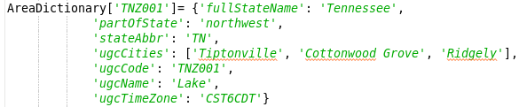 |
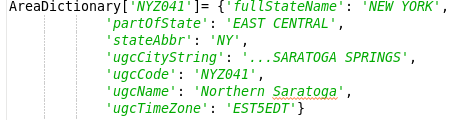 |
There are bodies of water in AreaDictionary in DefaultAreaDictionary.py that can be overridden too. An example of an editArea key being overridden for a body of water is shown below.
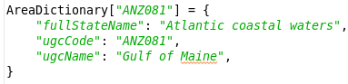
Two examples of individual keys in an editArea key of AreaDictionary being overridden are shown below.
Two examples of individual keys for a body of water in an editArea key of AreaDictionary being overridden are shown below.
Troubleshooting
Make sure the formatter has the Display Name set to something other than None in the lowest level override, usually SITE-level, Definition or Text Product file. Also make sure there isn't an override in the lowest-level override, usually SITE-level, Overrides file (if it exists for the Text Product) that has the Display Name set to None.
The above link goes to a Wiki created by Jonathan Lamb that explains what to do (how to troubleshoot) when a formatter fails.
You are getting undesirable results with the baseline formatter:
- If the problem is with a narrative phrase, check the TextRules Reference documentation to see if there are thresholds and variables that you might set to produce desired results.
You are getting undesirable results and you have overridden some thresholds and/or variables in your Overrides file:
- Run the baseline version of the product to see if you get the same results.
- If so, use the strategy above.
- If not, comment out the overrides in your Overrides file and run it as the baseline.
- Now begin adding in the overrides one-by-one until the problem re-occurs.
Other
For a particular edit area, you get the error the message: WARNING: TOO MANY PASSES ON TREE or WARNING EMPTY WORDS FROM TREE. These problems are often data-dependent making it difficult to reproduce, especially at another site. You will have to perform some detective work in order to isolate the problem. In these situations, the narrative product is not completing as intended. The multiple-pass processing has the potential of an infinite loop if the logic is such that some method either does not return a 'done' status or does not set the words for a phrase correctly. In either case, the strategy for locating the problem is the same. It is desired to locate the offending method, and turning on the "trace" flag will help determine the method that is being called repeatedly. However, before the trace messages are turned on isolate the problem as much as possible. This is done by isolating the edit time period and phrase method that are causing the trouble.
- Isolate the edit area for which there is a problem. Run the product for that area only by altering your Combination file or the "defaultEditAreas" list.
- Isolate the time period for which there is a problem. Override the issuance_list for the product and comment out all periods except the first for the issuance causing the problem. Run the product for this time period and see if you get the same error. If not begin uncommenting the periods one at a time until you get the error. For any components prior to the one causing the trouble override the product component definition and remove all the entries in the "analysisList" and "phraseList" variables.
- Isolate the phrase method. Determine which phrase is causing the problem by overriding the product component definition for the time period causing the trouble. Comment out all but the first phrase method and run the product. If the problem does not occur, begin uncommenting each phrase one-by-one and running the product until you find which phrase is causing the problem. Then comment out all but that phrase method and run the product again to see that the problem occurs. In some rare cases, you may have to uncomment more than one phrase to get the problem to occur.
- Check the offending phrase method code. Find the phrase "word" method in the TextRules Library (or your Overrides file if you have overridden or added methods) and ensure that all of its return statements return with a self.Done() call or a self.setWords() call. If not correct the code and run your product again. If that was not the problem, proceed to the next step.
- Turn on the trace messages. Now you can turn on the trace messages in your Overrides file by setting the Definition["trace'] flag to run. Re-run the product and examine the end of the trace messages. You are looking for a method that is repeating without returning a status of 'done' as reported in the message or is continually returning None for the value of 'Words' in the trace message. If you find the offending method, you can begin to investigate why it is not completing.
- Check your overrides. You will want to isolate which of your overrides introduces the problem.
Missing a Configured file
When a text formatter configured file is missing use the following steps that use the Hazard_AQA formatter as an example:
- In the Localization Perspective under the EDEX Folder, under the AFOS2AWIPS Folder:
- Make sure the line PHXAQAXXX AEUS75 KXXX is removed from the SITE version of afos2awips.blacklist.txt where XXX is your site id.
- Make sure the line PHXAQAXXX AEUS75 KXXX, where XXX is your site id, is added to the SITE version of afos2awips.txt
- Check the afosMasterPIL.txt and textCategoryClass.txt files located in /awips2/edex/data/utility/common_static/configured/XXX/textdb/ where XXX is your site id.
- Do this per the instructions in the AWIPS II System's Manager Manual (SMM) section 16.6.2.
- Make sure PHXAQAXXX, where XXX is your site id, is in afosMasterPIL.txt.
- Make sure AQA is in textCategoryClass.txt
- Touch one of the formatter files in common_static/base/gfe/textproducts/templates/product/
- For example, run in terminal touch /awips2/edex/data/utility/common_static/base/gfe/textproducts/templates/product/DGT.py . You might need to have your ITO or ESA do this for you.
- Touch the localConfig.py file in the Localization Perspective under the GFE Server Folder under the Server Config Files Folder
- Make a minor change, save localConfig.py, and then remove the minor change and save localConfig.py.
- Run in terminal /awips2/GFESuite/bin/configureTextProducts XXX as user awips on dv3, where XXX is your site id.
Utilities
Basics and How They Fit into the Smart Tools/Procedures/Text Infrastructure
Utilities are added Python modules that contain methods that are desired to be shared among Smart Tools, Procedures, Text Products, and Text Utilities. They are intended for code that is used in two or more GFE file types (i.e., Smart Tools, Procedures, Text Products, and Text Utilities). Utilities are less defined and have a less consistent structure than Smart Tools and Procedures. "Self" refers to a particular Utility's class instance. Make sure to list "self" as the first argument of method definitions (e.g., def myMethod(self, arg1, arg2)). When calling methods you created in the utility_class_name class, use self._methodName omitting self as the first argument (e.g., X = self._myMethod(arg1, arg2)). When changes are made to a Utility file, a CAVE restart is required for the changes to the Utility file to take effect.
To use a Utility in a Smart Tool, Procedure, Text Product, or Text Utility, at the beginning of the file, include import utility_name and in the file (usually in the preProcessTool section of a Smart Tool) insert self._utility_name= Utility_Name.Utility_Name(self._utility_arg1, self._utility_arg2, etc.) where utility_arg1 and utility_arg2 are the arguments in the Utility __init__ method. Then, in order to call the method, use self.utility_name._method_name(arg1, arg2, etc.). Some Utilities contain more than just methods that are used in Smart Tools, Procedures, Text Products, or Text Utilities. Utilities usually contain import SmartScript, often contain import numpy, almost always contain one import statement, and usually contain several other import statements. They usually inherit from a class which often is SmartScript. The SmartScript class, which is a Utility, is documented here. The utility_class_name class often contains the __init__ method even if it doesn't inherit from another class and often contains other methods. Utilities almost always inherit from some other class. Some Utilities contain multiple classes and contain multiple methods that aren't in a class. Also some Utilities contain configuration items outside of (not in) a class and don't contain a class. Utilities are primarily used in Smart Tools and Procedures and only a few are used in the Text Infrastructure. One of the main Utilities that is used in the Text Infrastructure is TextRules.
MakeHazardConfig
Another Utility file that is usually overridden is MakeHazardConfig.py. The MakeHazard.py Procedure imports the MakeHazardConfig.py Utility to create Hazard grids. When making changes to the MakeHazardConfig.py file, it is best to create a USER-level version of the file and test the changes in Practice Mode. Then if everything works correctly, you can copy the changes into the SITE-level file or move the file to the SITE-level. The MakeHazardConfig.py file can be used to configure contents of hazard categories, the maps that are used for each hazard category, and local effects (i.e. elevation-based hazards).
The MakeHazardConfig.py file contains a method called sortHazardList which takes a dictionary and sorts the entries in the menu in alphabetical order and returns a sorted dictionary table. This method uses the VTECTable.py file which is located in the /awips2/edex/data/utility/common_static/base/vtec/ directory. This method should not be modified. The next part of the MakeHazardConfig.py file contains a dictionary called hazardDict that is declared as an OrderedDict. The hazardDict dictionary for each hazard type contains the name of the hazard type (e.g., Winter Weather, Non-Precipitation, Fire Weather, etc.) followed by a list of hazard abbreviations (e.g., BZ.W, CF.A, AQ.Y, etc.) which are found in the VTECTable.py file. The hazard type names are the keys for the dictionary and are the menu entries on the MakeHazard Dialog. The hazard type names and the corresponding hazards for each hazard type can be modified as desired for your office. Often the hazard types that your office doesn't use are commented out. To minimize scrolling, you can change the order of the specific hazards in the list corresponding to a hazard type so that the most common hazards your site uses are near the beginning of the list. If your site is GUM, then in your SITE-level MakeHazardConfig.py file you will need to comment out the first hazardDict declaration and uncomment the second.
In the next section of the file the hazardDict dictionary is set equal to the output of running the sortHazardList method on hazardDict. This line in the file can be commented out if desired by your site. The next part of the MakeHazardConfig.py file contains a dictionary called mapNames. The mapNames dictionary contains the map categories and the associated names of the maps for that category. The categories, i.e. keys, in the mapNames dictionary must match the hazard types, i.e. keys, in the hazardDict dictionary. The <site> at the end of each of the map names is substituted with your site or the site that you are in Service Backup for. The names of each map must match the name of a map in the Localization Perspective under the CAVE Folder, under the Bundles Folder, under the maps Folder. In the next section of the file the defaultHazardType, mapColor, defaultMapWidth, areaThreshold, and timeScaleEndTime variables are defined. The defaultHazardType variable defines the hazard type that is selected when the MakeHazard GUI pops up after selecting MakeHazard under the Hazards menu in GFE. The defaultHazardType variable must be set equal to one of the hazard types and map categories (i.e., keys) and is often set equal to the Non-Precipitation hazard type but can be set equal to whatever hazard type is desired by your site. The mapColor variable defines the color to be used to indicate the selected areas (zones/counties) on the map. The default color is red and if your site desires the mapColor variable can be modified. The mapColor variable should not be set to black as that is the default color for unselected areas. The defaultMapWidth variable defines the initial map width of the map shown in the MakeHazard GUI. The default is 400 and this can be changed by your site to have a smaller or larger map in the MakeHazard GUI. The areaThreshold variable defines the percentage that an area must be covered to default to selected. The default is 0.10 (10%) and this can be changed if desired by your site. The timeScaleEndTime defines the duration in hours of the Hazard Start and End Time time scales. The default is 96 but this can be modified by your site to have either shorter or longer time scales for the Hazard Start and End Time. The areaThreshold and defaultMapWidth variables are not normally modified by sites. The next part of the MakeHazardConfig.py file contains the tcmList declaration. By default the tcmList variable is defined as an empty list. For sites that issue the HLS (i.e., Tropical sites) this line should be commented out and one of the four lines below it should be uncommented based on the location of your site. The final section of the file contains the localEffectAreas and localAreaData dictionary definitions.
localEffectAreas and localAreaData
If you add edit areas to the localEffectAreas dictionary, then they must also be in the localAreaData dictionary. The localEffectAreas dictionary consists of a list of edit areas associated with a particular hazard type (i.e., key). The localEffectAreas dictionary should not be used to define localEffectAreas entries for the Tropical Cyclone or Convective Watches hazard types. The edit areas that are used in the localEffectAreas often involve topography (e.g., Above1000, Below2000, etc.) or dams. To create an edit area that is dependent upon the topography of your CWA click the ? button on the GFE toolbar/button bar to open the Edit Area and Query Dialog. Then in the Query box type Topo, then the greater or less than sign, maybe an equals sign, and an elevation. To create your query, you can also select Topo from the Weather Elements box and use the symbols and numbers to the right of the three scroll boxes instead of typing everything. For example to create an edit area that includes everywhere that is greater than an elevation of 1000 ft, you could type Topo > 1000 in the Query box or you could select Topo from the Weather Elements scroll box, click the greater than sign, and a one and three zeros from the symbols and numbers to the right of the three scroll boxes, which is shown in the image below.
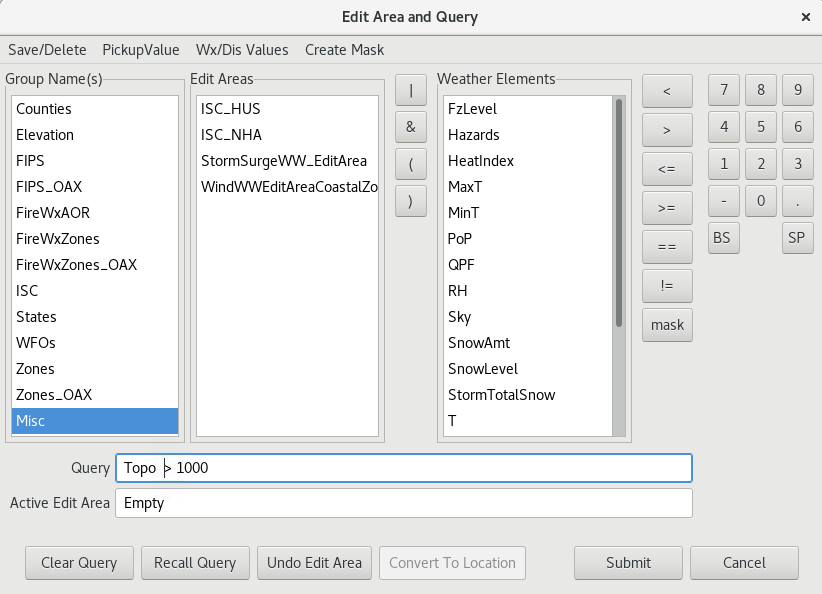
Once you have the query you want to use in the box, click Submit to generate the edit area. Prior to saving the edit area you MUST click Convert To Location or else the edit area won't be able to be read.
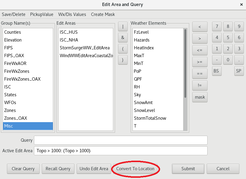
After you click Convert To Location, click Save/Delete, then select Save Edit Area... . Then type the name of the edit area (e.g., Above1000) in the identifier box. If desired, you can select a group from the included in Group Name(s) box or type one in the New Group box. Then click Save Active Area.
Each edit area in the localEffectAreas dictionary is a key for the localAreaData dictionary. Each edit area in the localAreaData dictionary is paired with a corresponding segment number, display name, and list of zones to be preselected when choosing that particular Local Effect Area in the MakeHazard GUI. The segment number is used to give headline and segment wording. For any special phrasing to appear in the final product, the formatter has to be coded to recognize the specific segment number and generate the desired phrase. For elevation based hazards the segment number is +/- 1 the elevation threshold for elevation edit areas. This means for an edit area named Above2500 the segment number will be 2501 or for an edit area named Below2500 the segment number will be 2499. The display name allows you to display a pretty string in the user interface rather than the edit area name. If the display name is an empty string (i.e., ""), then the edit area name will be used as the display name. If you do not want to preselect any zones after selecting the Local Effect Area, an empty list should be provided. Users can still change the zones so this should show all the zones the edit area covers or the most common zone combination.
Short History with SmartScript
- Jan 9, 2013 enableISCsend, clientISCSendStatus, manualSendISC_autoMode, and manualSendISC_manualMode were added.
- Jan 30, 2013 The TypeError in getGridCellSwath was fixed.
- Mar 13, 2013 Bulk getGrids was implemented to improve performance and performance improvements were made for the TCMWindTool.
- Jun 21, 2013 encodeEditArea was fixed to evaluate the query when necessary.
- Aug 14, 2013 encodeEditArea was fixed to return astype(numpy.bool8) so a mask can be used with advanced indexing (e.g., grid[mask] = value).
- Aug 24, 2013 UVToMagDir was fixed to work with scalar arguments and some constants in it were cleaned up.
- Oct 7, 2013 The use of pytz was removed.
- Oct 29, 2013 Getting Wx/Discrete keys in getGridResults was improved.
- Oct 31, 2013 A change was made to use DiscreteGridSlice.getKeys.
- Nov 7, 2013 getGridsResult was fixed for retrieving Wx/Discrete in First mode.
- Dec 23, 2013 The unloadWEs method was added.
- Apr 29, 2014 getGrids was fixed to return non-scalar grids as tuples in all cases.
- Nov 26, 2014 loadParm was corrected for a type error.
- Dec 1, 2014 The gmTime and localTime methods were added which are exact equivalents to those in the Python time module.
- Dec 1, 2014 getTimeZoneStr and getTzInfor were added which return the site's local time zone as a string or as an object respectively.
- Dec 1, 2014 createTimeRange was fixed to correctly return time ranges relative to local time regardless of setting of os.environ['TZ'].
- Jan 13, 2015 Optional parameter was added to availableParms to specify desired databases and createGrid was fixed to accept a DatabaseID for model.
- Apr 13, 2015 Smart Script was updated for the new JEP API.
- Jul 17, 2015 callSmartTool and callProcedure were updated to send Hashmap for varDict.
- Aug 13, 2015 NumpyJavaEnforcer support was added in createGrids and decodeEditArea and additional code cleanup was completed.
- Aug 26, 2015 Optional group parameter was added to editAreaList and callTextFormatter was added.
- Aug 27, 2015 saveCombinationFile and transmitTextProduct were added.
- Sep 11, 2015 Notification processing was removed from publishedElements.
- Sep 16, 2015 Modified varDict was returned from the called Smart Tool/Procedure.
- Jan 20, 2016 Type of mask returned from getComposite was fixed to work with numpy 1.9.2.
- Jan 28, 2016 Changes to IFPClient for support were made.
- Feb 22, 2016 Support for sendWFOMessage was added.
- Apr 5, 2016 Exception when attempting to create more than 256 Wx keys was added.
- May 6, 2016 Issue of contours plotted over ProposedWatches grid when ViewWCL is run was fixed.
- Aug 22, 2016 Operational text product in test mode was retrieved.
- Sep 28, 2016 loadCombinationsFile method was added and CombinationsFileUtil was moved to common.
- Oct 31, 2016 Cast to primitive for compatibility.
- Feb 6, 2017 Java .toString calls were removed.
- Jan 19, 2018 Smart Script was updated to reflect that Jep 3.6 now returns Python Floats as Doubles.
- Jan 24, 2018 Smart Script was changed to allow a new GFE config file to be selected when the perspective is reopened.
- Jan 31, 2018 Smart Script was updated for changes to ISCDataAccess.getCompositeGrid.
- Feb 6, 2018 Unnecessary extra publish call in publishElements and TypeError in officeType was fixed.
- Feb 7, 2018 Smart Script was changed to use ReferenceData.isEmpty.
- Apr 19, 2018 Smart Script was updated to rename and remove models.
- Oct 23, 2018 Import of JavaTimeRange was fixed.
- Apr 29, 2020 Use SiteMap.getSite4LetterId()